Sun Ultra 60 Service Manual
Page
Contents
Troubleshooting Procedures 4-14.1 Power-On Failure
Power On and Off
Contents
Storage Devices 9-19.1 Hard Drive
Illustrated Parts List 11-1 Product Specifications
Functional Description
Glossary G-1 Index
Figures
10-8
10-3
10-6
10-11
10-22
10-24
Figures
10-23
Tables
10-13
11-3
Mass Storage Device Power Estimates
How This Book Is Organized
Table P-1Document Organization
Unix Commands
Table P-2Typographic Conventions
Typographic Conventions
Shell Prompts
Table P-3Shell Prompts
Machinename#
Related Documents
Table P-4Related Documents
Accessing Sun Documentation Online
Ordering Sun Documentation
Sun Welcomes Your Comments
Page
Product Description
System unit
1Supported I/O Devices
System Unit Features
I/O Devices
CD-ROM drive Or tape drive Diskette drive Power LED
System Unit Components
3System Unit Rear View
2System Unit Replaceable Components
NVRAM/TOD
Page
SunVTS Overview
SunVTS Description
SunVTS Operation
1SunVTS Documentation
Power-On Self-Test
Pre-POST Preparation
1Diag-Level Switch Settings
Post Overview
Setting Up a Tip Connection
1Setting Up a TIP Connection
Verifying the Baud Rate
Initializing Post
2Sun Type-5 Keyboard
Maximum and Minimum Levels
Verify the following
Diag-levelVariable Set to max
Code Example 3-1 diag-levelVariable Set to max
Power-On Self-Test
Code Example 3-1 diag-levelVariable Set to max
Power-On Self-Test
Code Example 3-1 diag-levelVariable Set to max
Power-On Self-Test
Diag-levelVariable Set to min
Power-On Self-Test
Code Example 3-2 diag-levelVariable Set to min
Power-On Self-Test
Post Progress and Error Reporting
Code Example 3-3Typical Error Code Failure Message
0STATUS =FAILED 0TEST
Bypassing Post
2Keyboard LED Patterns
Additional Keyboard Control Commands
System and Keyboard LEDs
Initializing Motherboard Post
Page
Troubleshooting Procedures
Power-On Failure
Action
Video Output Failure
Disk Drive or CD-ROM Drive Failure
At the system ok prompt
1Internal Drives Identification
Power Supply Test
Supply Trip L
Dimm Failure
OpenBoot Prom On-Board Diagnostics
5DIMM Physical Memory Address
Watch-clock
Probe-scsi and probe-scsi-all
Test alias name, device path, -all
6Selected OBP On-Board Diagnostic Tests
UPA Graphics Card
OpenBoot Diagnostics
Ok% test screen
Verify that the OBDiag screen is displayed Code Example
1 PCI/Cheerio
Code Example 4-9PCI/Cheerio Output Message
Code Example 4-10EBus DMA/TCR Registers Output Message
EBus DMA/TCR Registers
Ethernet
Code Example 4-12Keyboard Output Message
Keyboard
Code Example 4-11Ethernet Output Message
Parallel Port
Mouse
Floppy
Code Example 4-13Mouse Output Message
Code Example 4-16Serial Port a Output Message
Serial Port a
Code Example 4-15Parallel Port Output Message
Code Example 4-16Serial Port a Output Message
Serial Port B
Code Example 4-18Serial Port B Output Message
Code Example 4-19NVRAM Output Message
Nvram
Audio
Audio Output Message
Scsi Output Message
Scsi
All Above
Code Example 4-22All Above Output Message
BAUDRATE=’1200’
Code Example 4-22All Above Output Message
Page
Safety and Tool Requirements
Safety Requirements
Symbols
Safety Precautions
Electrostatic Discharge Lithium Battery
Tools Required
Power On and Off
Powering On the System Unit
1System Unit Power-On Front Panel
Powering Off the System Unit
3System Unit Power-Off Front Panel
Internal Access
Removing the Side Access Cover
1Lock Block Location
2Removing the Side Access Cover
Attaching the Wrist Strap
Replacing the Side Access Cover
3Attaching the Wrist Strap to the Chassis
4Replacing the Side Access Cover
Page
Major Subassemblies
Power Supply
Removing the Power Supply
Replacing the Power Supply
1Removing and Replacing the Power Supply Part 1
Power on the system unit
PCI Fan Assembly
Removing the PCI Fan Assembly
Replacing the PCI Fan Assembly
3Removing and Replacing the PCI Fan Assembly
Hard Drive Bay With Scsi Assembly
Removing the Scsi Drive Bay
See .1.1, Removing a Hard Drive on
Replacing the Scsi Drive Bay
4Removing and Replacing the Scsi Drive Bay
See .1.2, Replacing a Hard Drive on
Removing the Peripheral Power Cable Assembly
Cable Assemblies
Replacing the Peripheral Power Cable Assembly
Removing the Diskette Drive Cable Assembly
Replacing the Diskette Drive Cable Assembly
EMI Filler Panels
Removing an EMI Filler Panel
Replacing an EMI Filler Panel
5Removing and Replacing the Bezel EMI Filler Panel
Chassis Foot
Removing the Foot
Replacing the Foot
Speaker Assembly
Removing the Speaker Assembly
Replacing the Speaker Assembly
8Removing and Replacing the Speaker Assembly
DC Switch Assembly
Removing the DC Switch Assembly
9System Unit Power-Off Front Panel
11Removing the Side Access Cover
12Attaching the Wrist Strap to the Chassis
Bracket tab PCI card
Bracket tab UPA graphics card
Remove the PCI fan assembly Figure
Remove the hard drives Figure
Major Subassemblies
Screw To terminator board Scsi cable
DC power connector DC power cable routing J3504
Screw Light pipe Bezel Nameplate
19Removing and Replacing the Front Panel
Replacing the DC Switch Assembly
20Removing and Replacing the Front Panel DC Switch Assembly
Page
See .1.2, Replacing a Hard Drive on
21Replacing the Side Access Cover
22System Unit Power-On Front Panel
CPU Fan Assembly
Removing the CPU Fan Assembly
Replacing the CPU Fan Assembly
24Removing and Replacing the CPU Fan Assembly
Shroud Assembly
Removing the Shroud Assembly
Replacing the Shroud Assembly
25Removing and Replacing the Shroud Assembly
See .1.3, Replacing the CPU Module on
Storage Devices
Hard Drive
Removing a Hard Drive
Replacing a Hard Drive
1Removing and Replacing a Hard Drive
Removable Media Assembly Drive
Removing the RMA
Attach the wrist strap
Removing the CD-ROM Drive or Any X-Option Tape Drive
2Removing and Replacing a RMA Drive Part 1
3Removing and Replacing a RMA Drive Part 2
Replacing the CD-ROM Drive or Any X-Option Tape Drive
Removing the Diskette Drive
Replacing the Diskette Drive
Replacing the RMA
Replace the side access cover
Motherboard and Component Replacement
Removing the CPU Module
CPU Module
Special Considerations for Systems With 450 MHz CPU Modules
Attach a wrist strap
Replacing the CPU Module
NVRAM/TOD
Removing the NVRAM/TOD
Replacing the NVRAM/TOD
2Removing and Replacing the NVRAM/TOD
PCI Card
Removing a PCI Card
3Removing and Replacing a PCI Card
Replacing a PCI Card
UPA Graphics Card
Removing the UPA Graphics Card
Replacing the UPA Graphics Card
4Removing and Replacing a UPA Graphics Card
Dimm
To remove and replace a DIMM, proceed as follows
Removing a Dimm
1DIMM Bank and Bank Quad
Dimm
Replacing a Dimm
Audio Card
Removing the Audio Card
See .4.1, Removing the UPA Graphics Card on
Replacing the Audio Card
6Removing and Replacing the Audio Card
Motherboard
Removing a Motherboard
7Removing and Replacing the Motherboard Part 1
Handle Captive screw
2Serial Port Jumper Settings
Replacing a Motherboard
J2801
Connect the following
Ok setenv #power-cycles
Illustrated Parts List
1System Unit Exploded View
1System Unit Replaceable Components
1System Unit Replaceable Components
Product Specifications
Table A-1System Unit Physical Specifications
Physical Specifications
Electrical Specifications
Table A-2Electrical Specifications
Environmental Requirements
Table A-3Environmental Requirements
Page
Signal Descriptions
Keyboard/Mouse and Serial
Keyboard/Mouse Connector
Table B-1Keyboard/Mouse Connector Pin Assignments
Ports a and B
Serial Port a and B RS-423/RS-232 Connectors
Used by the data terminal
CTS
Twisted-Pair Ethernet Connector
DTR
UltraSCSI Connector
Appendix B Signal Descriptions B-7
Table B-4UltraSCSI Connector Pin Assignments
Appendix B Signal Descriptions B-9
Audio Connectors
Parallel Port Connector
Headphones Line-out Line-in Microphone
2514
Appendix B Signal Descriptions B-13
Media Independent Interface Connector
Table B-7 MII Connector Pin Assignments
Table B-7MII Connector Pin Assignments
UPA Graphics Card Connector
Figure B-8 Table B-8
Table B-8UPA Graphics Card Connector Pin Assignments
Page
Functional Description
System Unit
PSYCHO+ Asic
UPA Interconnect
Table C-1UPA Port Identification Assignments
System Controller
3.1
3.2 Symbios 53C876 Scsi Controller
PCI Bus
Flash PROM/EPROM
EBus2 Devices
Cheerio Asic
SuperIO
UltraSPARC II Processor
Audio
Memory System
Memasel Membsel Memard Membrd Memawr Membwr
Memadra Weal RAS0L CAS0L
Figure C-5DIMM Mapping
Dimm
Table C-2DIMM Bank-to-U-Number Mapping
Table C-3IL = 0, Dimm Bank-to-Physical Address Mapping
Graphics and Imaging
Memory System Timing
Graphics Card Performance
Graphics Card Features
Peripherals
CD-ROM Drive
Diskette Drive
Diskette Drive Signals
Table C-4Diskette Drive Signals and Functions
Hard Drives
Table C-5Supported Hard Drives
Keyboard and Mouse Port
Other RMA Storage Device X-Options
Keyboard and Mouse, Diskette, and Parallel Port
Diskette Port
Parallel Port
Parallel Port Cables
Serial Port
Serial Port Components
Serial Port Functions
Synchronous Rates
Automatic Negotiation
External Transceivers
Connectors
12.5 MII Power
External Cables
PHY
Audio Card and Connector
Table C-6Audio Card Features
Linl
Figure C-10Configuration for the Scsi Bus
Host Adapter
Supported Target Devices
Table C-7Supported Target Devices
Internal Scsi Subassembly
Figure C-11 Scsi Subassembly Functional Block Diagram
15.1 K9+
ASICs
Scsi ID Selection
PSYCHO+
Marvin
Cheerio
15.5 FBC
Risc
Table C-8Power Supply Output Values
SuperIO
Table C-9Power Supply Control Signal
Control Signals
Remote Enable PowerOn and PowerOff
1.2 On/Off Functionality
Turning the System Unit On
System Unit Power Budget
Turning the System Unit Off
Table C-10300-MHz 3.3-ns CPU Modules Power Estimate
Table C-11PCI Card 5 Vdc Power Estimate
Table C-14Mass Storage Device Power Estimates
Table C-12PCI Card 3.3 Vdc Power Estimate
Table C-13Memory Subsystem Power Estimate
Built-In Speaker Specifications
Built-In Speaker
Standard System Facilities
TPE
Figure C-13Selected Jumper Settings
Jumper Descriptions
Table C-16Serial Port Jumper Settings
Serial Port Jumpers
Flash Prom Jumpers
Flash Prom Jumper Settings
Enclosure
Enclosure Basics
Agency Compliance
Enclosure Features
Environmental Compliance
Energy Star Software Support
Appendix C Functional Description C-49
Page
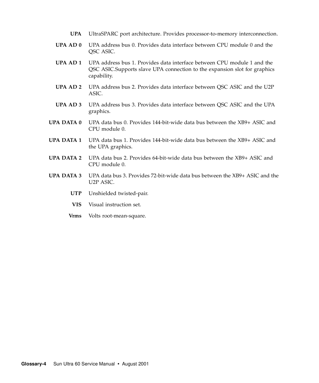
Glossary
Data terminal equipment
Insulation displacement connector
Dual tag or data tag
Extended capability port. An IEEE.1284 standard
Glossary-3
QSC Asic
Index
Agency compliance, C-48all above Output message
CPU
Address bus, C-5 Data bus, C-5
MII
Index-5
QSC ASIC, C-34
Pin assignments, B-3
Index-8