Sundance Technology
ST201
PRELIMINARY draft 2
dress register. Setting the ReceiveBroadcast and ReceiveMulticast bits in the ReceiveMode register will allow the ST201 to receive all broadcast and multicast frames, respectively. The ReceiveMultic- astHash bit in ReceiveMode enables a filtering mechanism for Ethernet multicast frames. This fil- tering mechanism uses a
Additionally, Ethernet frames containing IP multi- cast destination addresses can also be received by setting the ReceiveIPMulticast bit in the Receive- Mode register. IP multicast, or Host Extension for IP Multicasting, datagrams map to frames with Ethernet destination addresses of 0x01005e****** (where * represents any hexadecimal value).
The MACCtrl register is used to configure parame- ters including full duplex, flow control, and statistics gathering.
The ST201 can operate in either half duplex or full duplex mode. In half duplex mode, the ST201 implements the CSMA/CD algorithm. CSMA/CD requires that only one node transmit at a time. If multiple nodes attempt to transmit simultaneously (indicated when both the receive and transmit sig- nals are active) a collision will occur resulting in frame loss, and typically requiring
The IEEE 802.3x Full Duplex standard defines a special frame known as the PAUSE MAC Control frame. The PAUSE frame is used to implement flow control in full duplex networks allowing sta- tions on opposite ends of a full duplex link the abil-
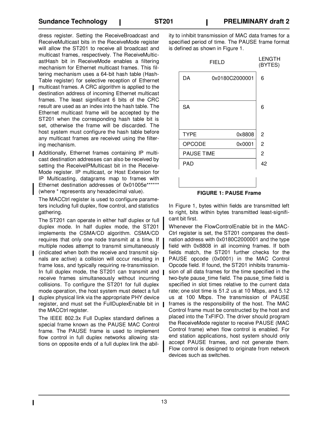
ity to inhibit transmission of MAC data frames for a specified period of time. The PAUSE frame format is defined as shown in Figure 1.
| FIELD | LENGTH |
| (BYTES) | |
|
| |
|
|
|
DA | 0x0180C2000001 6 | |
SA | 6 |
|
|
| TYPE | 0x8808 | 2 | |
|
|
|
|
|
| OPCODE | 0x0001 | 2 | |
|
|
|
|
|
| PAUSE TIME |
| 2 | |
|
|
|
|
|
| PAD |
| 42 | |
|
|
|
|
|
|
|
|
|
|
|
|
|
|
|
FIGURE 1: PAUSE Frame
In Figure 1, bytes within fields are transmitted left to right, bits within bytes transmitted
Whenever the FlowControlEnable bit in the MAC- Ctrl register is set, the ST201 compares the desti- nation address with 0x0180C2000001 and the type field with 0x8808 in all incoming frames. If both fields match, the ST201 further checks for the PAUSE opcode (0x0001) in the MAC Control Opcode field. If found, the ST201 inhibits transmis- sion of all data frames for the time specified in the
13
