EEPROMCTRL | |
Class | I/O Registers, External Interface Control |
Base Address | IoBaseAddress register value |
Address Offset | 0x36 |
Access Mode | Read/Write |
Width | 16 bits |
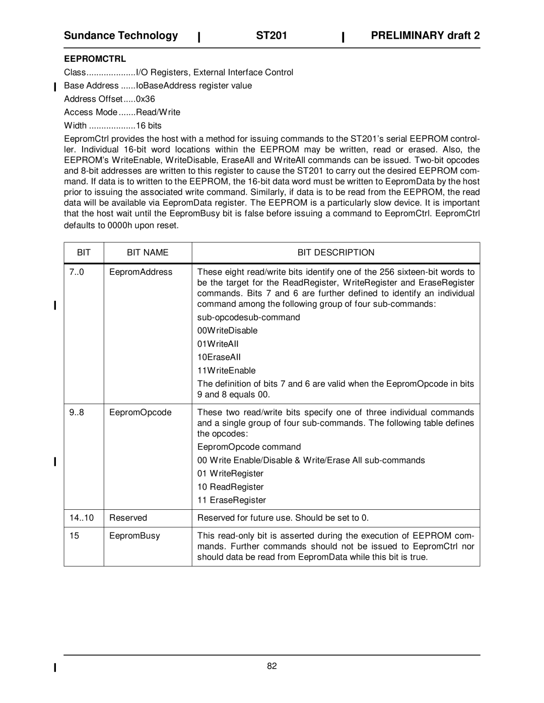
EepromCtrl provides the host with a method for issuing commands to the ST201’s serial EEPROM control- ler. Individual 16-bit word locations within the EEPROM may be written, read or erased. Also, the EEPROM’s WriteEnable, WriteDisable, EraseAll and WriteAll commands can be issued. Two-bit opcodes and 8-bit addresses are written to this register to cause the ST201 to carry out the desired EEPROM com- mand. If data is to written to the EEPROM, the 16-bit data word must be written to EepromData by the host prior to issuing the associated write command. Similarly, if data is to be read from the EEPROM, the read data will be available via EepromData register. The EEPROM is a particularly slow device. It is important that the host wait until the EepromBusy bit is false before issuing a command to EepromCtrl. EepromCtrl defaults to 0000h upon reset.
BIT NAME
EepromAddress
EepromOpcode
Reserved
EepromBusy
BIT DESCRIPTION
These eight read/write bits identify one of the 256 sixteen-bit words to be the target for the ReadRegister, WriteRegister and EraseRegister commands. Bits 7 and 6 are further defined to identify an individual command among the following group of four sub-commands:
sub-opcodesub-command
00WriteDisable
01WriteAII
10EraseAII
11WriteEnable
The definition of bits 7 and 6 are valid when the EepromOpcode in bits 9 and 8 equals 00.
These two read/write bits specify one of three individual commands and a single group of four sub-commands. The following table defines the opcodes:
EepromOpcode command
00Write Enable/Disable & Write/Erase All sub-commands
01WriteRegister
10ReadRegister
11EraseRegister
Reserved for future use. Should be set to 0.
This read-only bit is asserted during the execution of EEPROM com- mands. Further commands should not be issued to EepromCtrl nor should data be read from EepromData while this bit is true.

