Sundance Technology
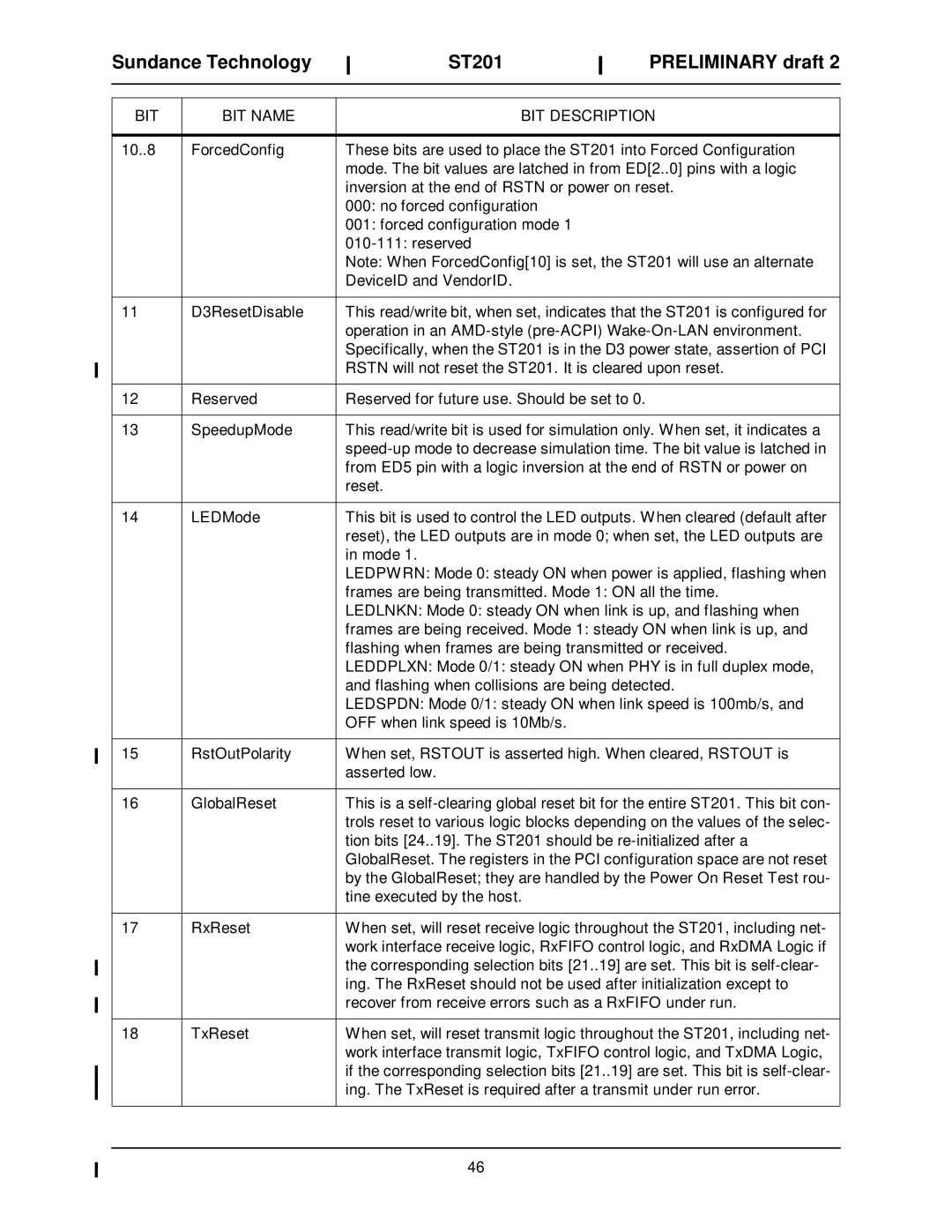
BIT | BIT NAME |
10..8 | ForcedConfig |
11D3ResetDisable
12Reserved
13SpeedupMode
14LEDMode
15RstOutPolarity
16GlobalReset
17RxReset
18TxReset
ST201 |
| PRELIMINARY draft 2 |
|
BIT DESCRIPTION
These bits are used to place the ST201 into Forced Configuration mode. The bit values are latched in from ED[2..0] pins with a logic inversion at the end of RSTN or power on reset.
000:no forced configuration
001:forced configuration mode 1
Note: When ForcedConfig[10] is set, the ST201 will use an alternate DeviceID and VendorID.
This read/write bit, when set, indicates that the ST201 is configured for operation in an
Reserved for future use. Should be set to 0.
This read/write bit is used for simulation only. When set, it indicates a
This bit is used to control the LED outputs. When cleared (default after reset), the LED outputs are in mode 0; when set, the LED outputs are in mode 1.
LEDPWRN: Mode 0: steady ON when power is applied, flashing when
frames are being transmitted. Mode 1: ON all the time.
LEDLNKN: Mode 0: steady ON when link is up, and flashing when
frames are being received. Mode 1: steady ON when link is up, and flashing when frames are being transmitted or received. LEDDPLXN: Mode 0/1: steady ON when PHY is in full duplex mode, and flashing when collisions are being detected.
LEDSPDN: Mode 0/1: steady ON when link speed is 100mb/s, and OFF when link speed is 10Mb/s.
When set, RSTOUT is asserted high. When cleared, RSTOUT is asserted low.
This is a
When set, will reset receive logic throughout the ST201, including net- work interface receive logic, RxFIFO control logic, and RxDMA Logic if the corresponding selection bits [21..19] are set. This bit is
When set, will reset transmit logic throughout the ST201, including net- work interface transmit logic, TxFIFO control logic, and TxDMA Logic, if the corresponding selection bits [21..19] are set. This bit is
46