Chapter 2: Installation and | Cabling |
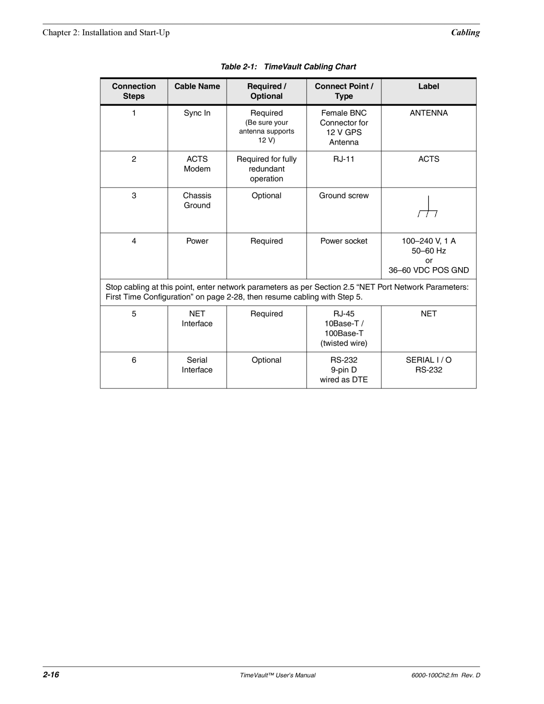
Table 2-1: TimeVault Cabling Chart
Connection | Cable Name | Required / | Connect Point / | Label |
Steps |
| Optional | Type |
|
|
|
|
|
|
1 | Sync In | Required | Female BNC | ANTENNA |
|
| (Be sure your | Connector for |
|
|
| antenna supports | 12 V GPS |
|
|
| 12 V) | Antenna |
|
|
|
|
|
|
2 | ACTS | Required for fully | ACTS | |
| Modem | redundant |
|
|
|
| operation |
|
|
|
|
|
|
|
3 | Chassis | Optional | Ground screw |
|
| Ground |
|
|
|
|
|
|
|
|
4 | Power | Required | Power socket | |
|
|
|
| |
|
|
|
| or |
|
|
|
|
|
|
|
|
|
|
Stop cabling at this point, enter network parameters as per Section 2.5 “NET Port Network Parameters: First Time Configuration” on page
5 | NET | Required | NET | |
| Interface |
|
| |
|
|
|
| |
|
|
| (twisted wire) |
|
|
|
|
|
|
6 | Serial | Optional | SERIAL I / O | |
| Interface |
| ||
|
|
| wired as DTE |
|
|
|
|
|
|
TimeVault™ User’s Manual |