Cabling | Chapter 2: Installation and |
2.2Cabling
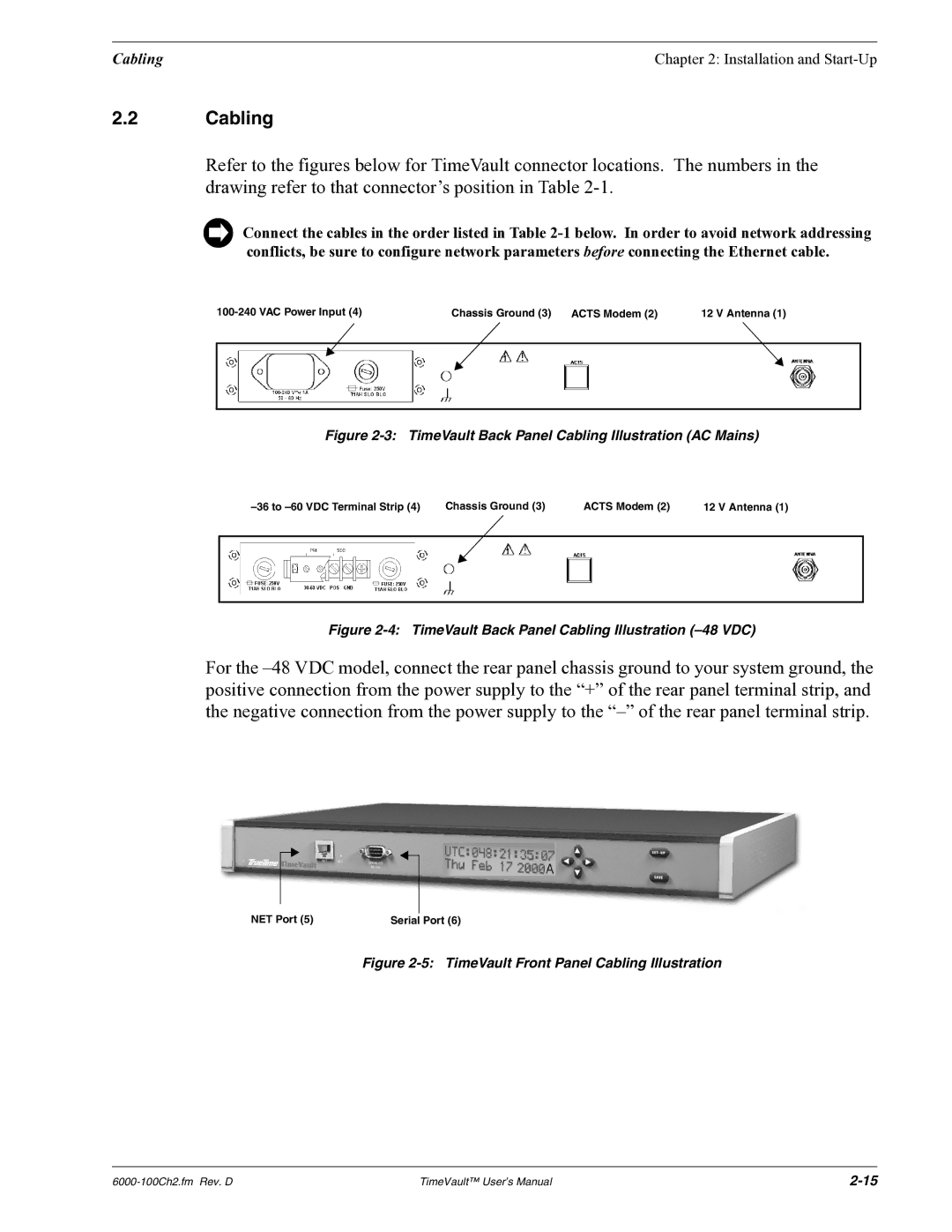
Refer to the figures below for TimeVault connector locations. The numbers in the drawing refer to that connector’s position in Table
Connect the cables in the order listed in Table
Chassis Ground (3) ACTS Modem (2) | 12 V Antenna (1) | |||||||
|
|
|
|
|
|
|
|
|
|
|
|
|
|
|
|
|
|
|
|
|
|
|
|
|
|
|
|
|
|
|
|
|
|
|
|
|
|
|
|
|
|
|
|
|
Figure 2-3: TimeVault Back Panel Cabling Illustration (AC Mains)
|
| Chassis Ground (3) | ACTS Modem (2) | 12 V Antenna (1) | |||||
|
|
|
|
|
|
|
|
|
|
|
|
|
|
|
|
|
|
|
|
|
|
|
|
|
|
|
|
|
|
|
|
|
|
|
|
|
|
|
|
|
|
|
|
|
|
|
|
|
|
|
|
|
|
|
|
|
|
|
|
|
|
|
|
|
|
|
|
|
|
Figure 2-4: TimeVault Back Panel Cabling Illustration (–48 VDC)
For the
NET Port (5) | Serial Port (6) |
Figure 2-5: TimeVault Front Panel Cabling Illustration
TimeVault™ User’s Manual |