Chapter 3: Remote Operation | Serial Access |
3.3Serial Access
The
Serial time output is not available on the Utility Port.
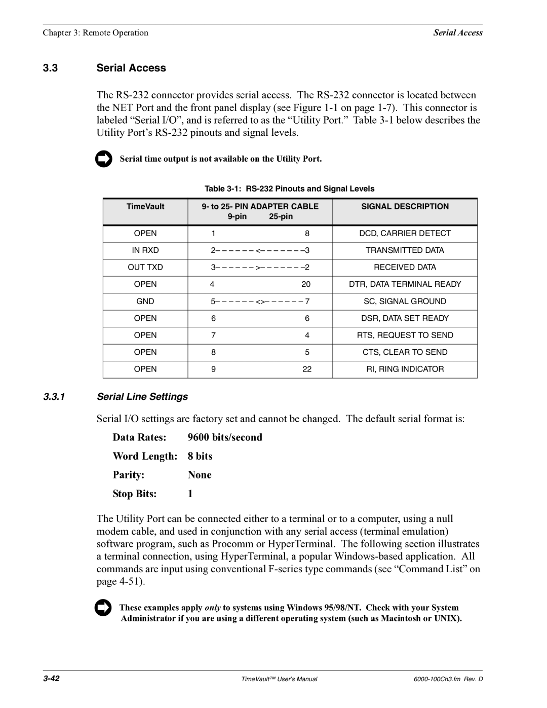
Table
TimeVault | 9- to 25- PIN ADAPTER CABLE | SIGNAL DESCRIPTION | |
|
|
|
|
|
|
|
|
OPEN | 1 | 8 | DCD, CARRIER DETECT |
|
|
| |
IN RXD | 2– – – – – – <– – – – – – | TRANSMITTED DATA | |
|
|
| |
OUT TXD | 3– – – – – – >– – – – – – | RECEIVED DATA | |
|
|
|
|
OPEN | 4 | 20 | DTR, DATA TERMINAL READY |
|
|
| |
GND | 5– – – – – – <>– – – – – – 7 | SC, SIGNAL GROUND | |
|
|
|
|
OPEN | 6 | 6 | DSR, DATA SET READY |
|
|
|
|
OPEN | 7 | 4 | RTS, REQUEST TO SEND |
|
|
|
|
OPEN | 8 | 5 | CTS, CLEAR TO SEND |
|
|
|
|
OPEN | 9 | 22 | RI, RING INDICATOR |
|
|
|
|
3.3.1Serial Line Settings
Serial I/O settings are factory set and cannot be changed. The default serial format is:
Data Rates: | 9600 bits/second |
Word Length: | 8 bits |
Parity: | None |
Stop Bits: | 1 |
The Utility Port can be connected either to a terminal or to a computer, using a null modem cable, and used in conjunction with any serial access (terminal emulation) software program, such as Procomm or HyperTerminal. The following section illustrates a terminal connection, using HyperTerminal, a popular
These examples apply only to systems using Windows 95/98/NT. Check with your System Administrator if you are using a different operating system (such as Macintosh or UNIX).
TimeVault™ User’s Manual |