Site Preparation
2.1.3Antenna Information
Voltage Requirement and Signal Levels
TimeVault requires a 12 V antenna. Any antenna that does not support 12 V may be severely damaged if plugged into TimeVault.
The GPS Synchronized Receiver, integral to TimeVault, operates on the L1 (1575.42 MHz) signal and the C/A code (1.023 MHz bit rate) with a minimum signal level of
Chapter 2: Installation and
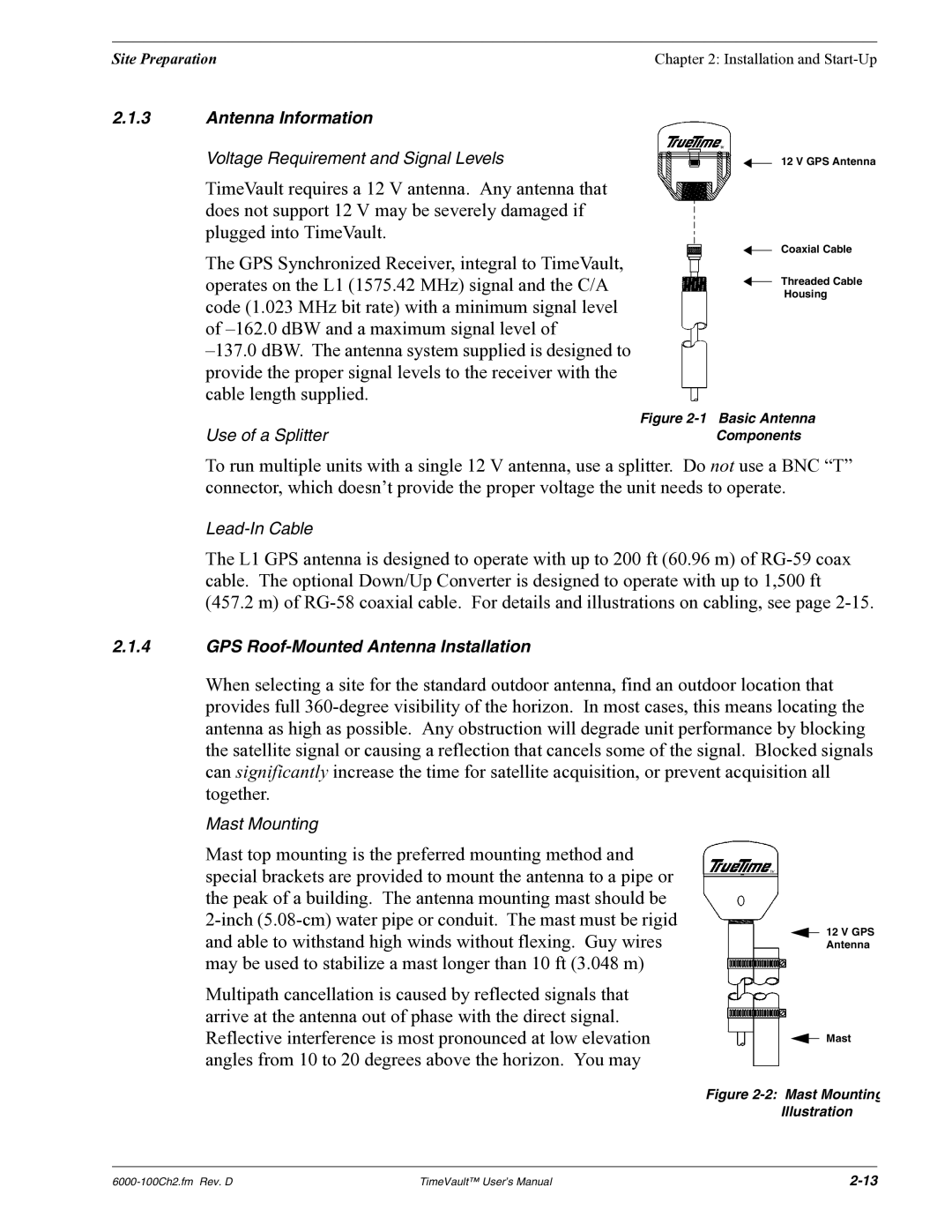
12 V GPS Antenna
Coaxial Cable
Threaded Cable
Housing
Use of a Splitter | Figure |
Components |
To run multiple units with a single 12 V antenna, use a splitter. Do not use a BNC “T” connector, which doesn’t provide the proper voltage the unit needs to operate.
The L1 GPS antenna is designed to operate with up to 200 ft (60.96 m) of
(457.2 m) of
2.1.4GPS
When selecting a site for the standard outdoor antenna, find an outdoor location that provides full
Mast Mounting
Mast top mounting is the preferred mounting method and special brackets are provided to mount the antenna to a pipe or the peak of a building. The antenna mounting mast should be
Multipath cancellation is caused by reflected signals that arrive at the antenna out of phase with the direct signal. Reflective interference is most pronounced at low elevation angles from 10 to 20 degrees above the horizon. You may
12 V GPS Antenna
Mast
Figure 2-2: Mast Mounting Illustration
TimeVault™ User’s Manual |