46 | 4 Configuring the system |
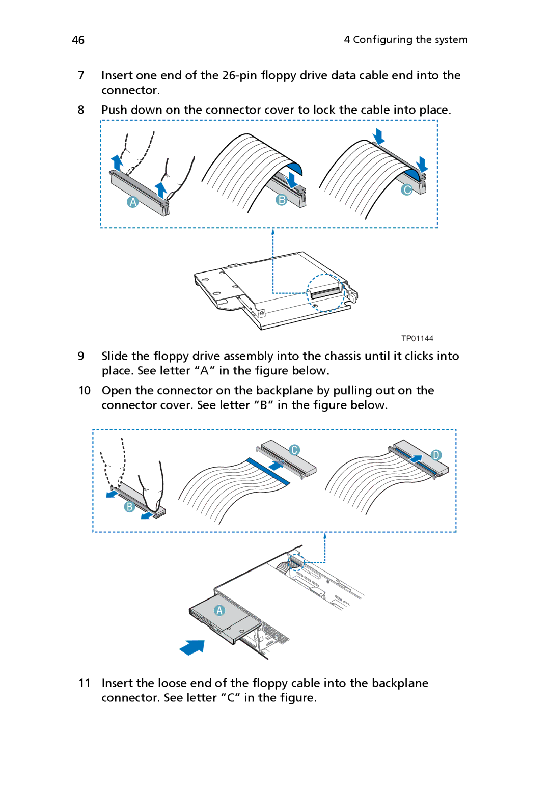
7Insert one end of the
8Push down on the connector cover to lock the cable into place.
A ![]() B
B
C
TP01144
9Slide the floppy drive assembly into the chassis until it clicks into place. See letter “A” in the figure below.
10Open the connector on the backplane by pulling out on the connector cover. See letter “B” in the figure below.
11Insert the loose end of the floppy cable into the backplane connector. See letter “C” in the figure.