7.4 Sub-programs
Blocks 1 through 5 are comments.
Blocks 6 through 8 define common defaults.
Block 9 defines the blockform or stock size. This is only needed for the 3D solid. The stock defined is 6x6 with center at 0,0.
Block 10 defines the initial roughing tool which has a 1" diameter.
The parameters for this tool must either come from the tool table or be saved in the tool table. This is a requirement for the coarse tool feature.
Blocks 11 through 13 define RPM and turn on the spindle and coolant.
Block 15 defines an island in
The island must always be programmed before the corresponding pocket. Also note that the island must specify the machining. In this case, since the island profile is defined in a clockwise orientation, the machining side is to the left (see block 26).
Block 16 is a 4x5 rectangular pocket with center at 0, 0. Note that finish stock is specified and the cycle is requested to skip the finish pass. This is required for the stand alone finish cycle.
Block 17 defines the finer roughing tool which a 1/4” diameter.
Block 18 defines the island for the finer roughing tool.
Block 19 defines the pocket for the finer roughing tool with the specification of the coarsetool=1.
Specifying the coarse tool as tool #1 allows the pocket cycle to calculate the material left by the coarse tool and only machine the required material. Also note that finish stock is specified and the cycle is requested to skip the finish pass. This is required for the stand alone finish cycles.
Block 20 defines the finish tool which a 1/4” diameter. Finishing could be done with the same tool but for illustration purposes a different tool is used.
Block 21
Block 22 is the
Block 23
Block 24 is the
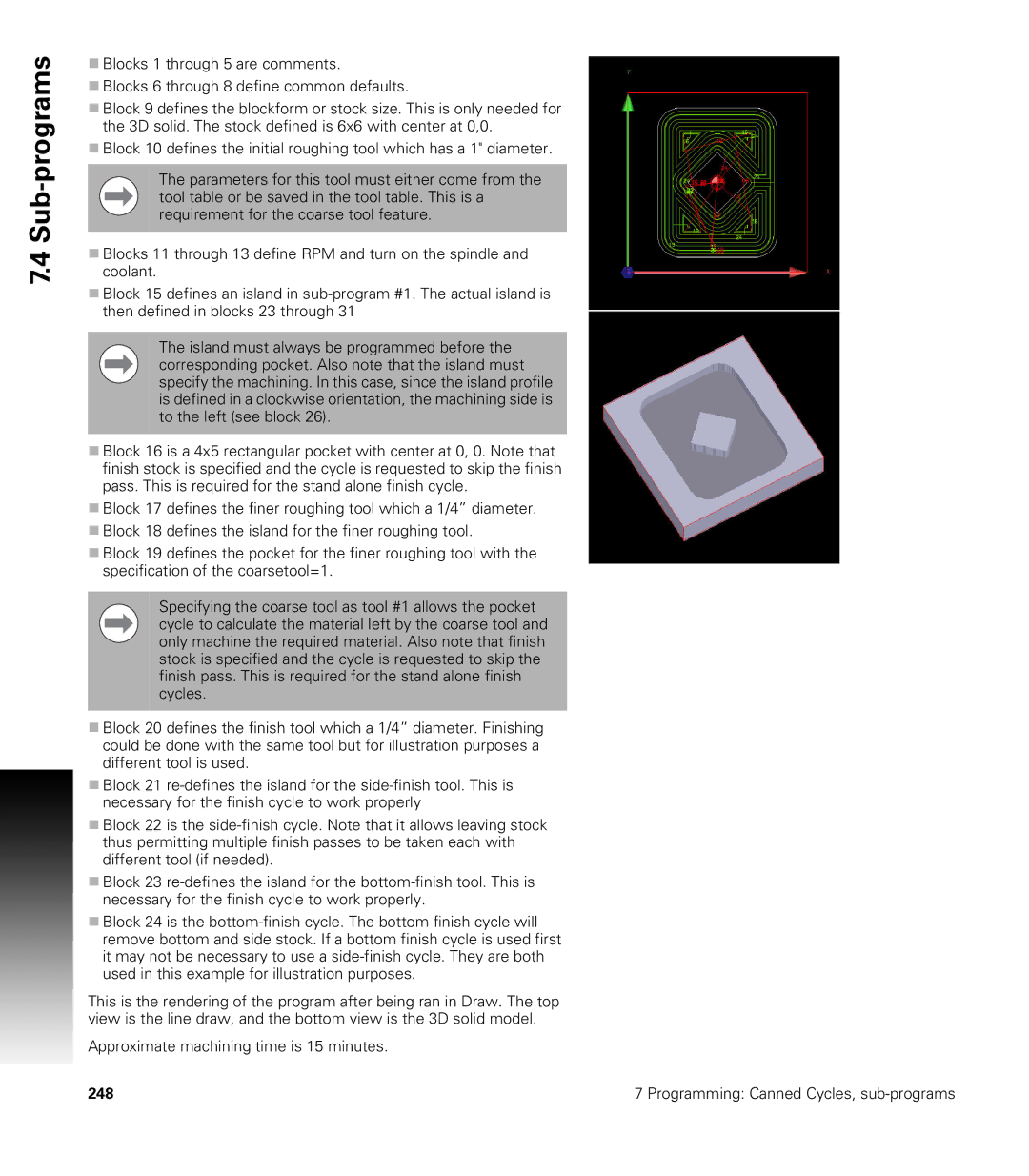
This is the rendering of the program after being ran in Draw. The top view is the line draw, and the bottom view is the 3D solid model.
Approximate machining time is 15 minutes.
248 | 7 Programming: Canned Cycles, |
