CNC
Page
Page
Controls
Controls
Axis Jog keys KeyFunction
Navigation keys KeyFunction
Keyboard Installation
Keyboard Equivalent Key Strokes Function
Alt + c
Arrows
Message symbols
Manual Information
Model, Software and Features
CNC model NC software number
Intended place of operation
Viii
New Functions of Software
689
Changed Functions of Software
Contents
Xii
Table of Contents
Machining Fundamentals
Xiv
Manual Data Input
Tool Data
Xvi
Program Management
Xvii
Programming Canned Cycles, sub-programs
Xviii
Probing Cycles
3500i
Drawing Programs
Running a Program on the Machine
Xxii
Xxiii
Code Edit, Help, & Advanced Features
Xxiv
Advanced Programming
Xxv
11.5 Four Axis Programming
Xxvi
Introduction
ACU-RITE conversational, and G-code formats
Introduction
Powering Up the CNC Machine
Stop, Servo Reset, and CNC Shutdown
Activating/Resetting the Servos
Reset the servos as follows
Emergency Stop E-STOP
Writing Programs
Operating Panel with Touch Screen display
Visual Display Unit
Screen Navigation
Operator Prompts
Menus, Dialogues, and Forms
Cursor
General Operating Guidelines
Main Operating Modes
Sub Modes
Visual
Display Unit
Upper Menu and Status Information Bar
Machine function buttons
Keyboard
Additional Buttons
Unit
Special Characters
Programming Sliders
Numeric touch pad
Drag Bar
Calculator
Advanced Function buttons
Using Context Sensitive Help
Context Sensitive Help
Button Function
Console Key Pad
Display navigation
Operating Mode Screens Main Operating Mode Screens
Manual Data Input
Mode Screens
Program Management Screen
Program Run
Draw View
Touch probes
Accessories
TS 220, TS 640 and TS 440 touch trigger probes
Electronic Edge Finder
HR electronic hand wheels
TT 140 tool touch probe for tool measurement
Machining Fundamentals
Fundamentals of Positioning
Position encoders and reference marks
Reference system
Reference system on milling machines
Polar coordinates
Designation of the axes on milling machines
Tool axis Principal axis Minor axis
Setting the pole and the angle reference axis
Angle Measurements
Absolute work piece positions
Absolute and incremental work piece positions
Incremental work piece positions
Setting the datum
Fixture Offsets
Fundamentals of Positioning
Jog Mode Moves
Manual Machine Positioning
Adjusting the Feedrate
Overriding the Spindle RPM
Manual Machine Positioning
Manual Data Input
Overview
Manual Data Input MDI
Manual Data Input Screen
Manual Data Input Mode Settings
Modes set from the Manual Data Input screen
Manual Data Input Menu Bar
MDI Menu Page two
Manual Data Input Operations
Mill Arc manual data input
Mill Arc manual data input View
Manual Data Input Cycles
Drill Cycles
Pocket Cycle Example
Rectangular Pocket Cycle data input View
Block History
Code MDI
MDI Touch Screen Feature Dialogues
Zero Axes
Program Preset
Move to Target Location
Tool
Offset
Basic Modals
Feed and Speed
Manual Data Input MDI
MDI Teach
Button Function
Tool Management
Tool Table / Tool Management
Tool Table
Tool Compensation Required Data
Locating the Tool Table
Tool numbers / Tool names
Sign for the length difference ΔL
Editing the tool table
Tool Table Menu Bar
Second Menu Bar
Clearing an entire line of tool data
Clearing the current tool table
Finding a tool using text
Find
Clear Feature
Teach, and Teach Program
Tool Table Structure
Feeds & Speeds Overview
Feeds & Speeds Table
Feeds & Speeds Table Structure
Column Description Tool Number
Tool Diameter
Tool Length
Number
Using the Feeds & Speeds Table
Simulation Tool and Offset Tables
Tool Data
Codes, and Tool Activation
Activating Offsets via the Program
T1 Format Description
Tool-Length Offsets
Entering Tool Length Offsets in the Tool Table
Diameter Offset in Tool Table
Tool Radius Compensation
Contouring without radius compensation
Contouring with radius compensation
Radius compensation Machining corners
Line Tangent Entry Move
Ramping into a Compensation Move
Line Perpendicular Entry Move
Arc Tangent Entry Move
Line Arc Tangent Entry Move
Special Code Temporary Change of Tool Diameter
Tool Compensation Path
Path of Tool During Tool Compensation
Intersecting Points
Compensation Around Acute Angles
General Precautions
Tool Life Management
Fixture Offsets Tool menu
Activate Tool Life Management
Replacement Tool RT
Lock, or Unlock a Tool
Tool Data
Program Management
Program Management Introduction
Accessing Program Management
Program Screen Description
Program Manager Menu Bar
Utility Function Buttons
Display window arrangement
Folder Filter
Program Manager Functions
Advanced Folder Filter
Utility Button Functions
Preview button
Paste Program button
Sorting Folder Contents
Program Properties
USB Access
Recycle Bin
Creating a New Part Program
Creating, Editing, & Selecting to Run
Editing an Existing Part Program
Selecting a Program To Run
Program selection
Conversational Editing
Conversational Programming
Getting Started
Direct
From Draw
Program Edit Screen
101
Program Edit buttons
Milling Button
Conversational Data Input Cycles
103
Milling Feature Buttons
More Milling Button
105
Drill Features Button
Pocket Cycles Button
107
Other Cycles Button
RMS
Program Editing
Mark a program block
Unmark a block, or blocks
109
Deleting a program block
Inserting a program block
Canceling edits to a program block
Copy/Paste Blocks in a program
Moving Blocks in a program
111
Restore edits to a program block
Editing an existing block
Find Specific Text or Code in a program
Program Text Editing
113
Program Edit Preview
Preview Side Bar Menu
Preview Features Menu
115
Program / Display Relation
Programming Canned Cycles, sub-programs
Explaining Basic Cycles
Round/Chamfer
Corner Rounding
Line-to-Line Corner Rounding
Line-to-Arc Corner Rounding
Arc-to-Arc Corner Rounding
Chamfering
119
Rapid
Rapid Move
Rapid Move EndPoint
Field Code Description
Rapid Move Angle
Rapid Move Angle and Radius
121
Rapid Move Angle and Y
Rapid Move Radius
Line
Rapid Move Radius and Y
Line Move
123
Line Move EndPoint
Line Move Angle
Line Move Angle and Radius
125
Line Move Angle and Y
Line Move Radius
Line Move Radius and Y
127
Arc
Arc Move
Arc Move Radius and EndPoint
129
Arc Move Center and EndPoint
Arc Move Center and Angle
131
Using Arc Center and EndPoint to create a circle
Dwell
133
Plane Selection
Reference Point Return
135
Fixture Offset Work Coordinate System Select
Unit Inch/MM
Dimension Abs/Inc
137
Absolute Zero Set
Block Form
139
Temporary Path Tolerance
System Data
141
FeedRate
FeedRate 4th-Axis
Functions
Spindle RPM
143
Tool Definition and Activation
Block Description
Repeat Blocks
145
0000
Canned Cycles
Canned Cycles
147
Drilling, Tapping, and Boring
Drilling Cycles
Basic Drill Cycle
Peck Drill Cycle
Counterbore Drill Cycle
149
Tapping Cycle
Boring Unidirectional Cycle
Boring Bidirectional Cycle
151
Chip Break Cycle
Flat Bottom Boring Cycle
153
Drill Bolt Hole Cycle
Drill Pattern Cycle
155
Milling Cycles
Mill Cycle
157
EndMill Cycle
Face Mill Cycle
159
160
Hole Mill Cycle
161
Thread Mill Cycle
163
164
Circular Profile Cycle
165
166
Rectangular Profile Cycle
167
168
Pocket Cycle Overview
Pocket Cycles
169
Draft Angle Pocket Cycle
171
Rectangular Pocket Cycle
173
Circular Pocket Cycle
175
Plunge Rectangular Pocket Cycle
177
Plunge Circular Pocket Cycle
179
Frame Pocket Cycle
181
Ring Pocket Cycle
183
Slot Cycle
185
Circular Slot Cycle
187
Irregular Pocket Cycle
189
Islands
Bottom Finish
191
Side Finish
Programming the Engrave Cycle
Engraving Cycles
193
194
Programming the Arc Engrave Cycle
195
’clock position. Optional
Tool, and Spindle Probe cycles
Probing Cycles
197
Tool Probe Cycles
Tool Probe Calibration Cycle
199
200
Tool Length and Diameter Offset Preset
201
202
203
To use the automatic tool preset
205
206
207
Manual Tool-Length Offset Preset
209
210
Manual Tool Diameter Measure for Special Tools
211
212
213
Tool Breakage, Length and Diameter Wear Detection
215
216
Spindle Probe Settings
Spindle Probe
Spindle Probe Cycles
217
Spindle Probe Calibration Cycle
219
Edge Finding
Outside Corner Finding
221
222
Inside Corner Finding
223
224
Inside/Outside Boss/Hole Finding
225
226
Inside/Outside Web Finding
227
228
Protected Probe Positioning
229
Skew Compensation
231
232
Using the Z Work Offset Update Feature
233
Sub-programs
Sub-program information
Overview
Ending the Main Program
Defining a sub-program
Ending a sub-program
Calling a sub-program
235
Looping a sub-program
Rotate, Mirror, and/or Scale a sub-program
237
238
Pocket/Island example
Pocket and Islands example
239
240
241
242
243
244
245
246
247
248
249
250
251
252
Drawing Programs
Draw
Viewing Programs
Starting Draw
255
View Options Menu
Adjust View Menu
257
Adjust Block Form
Zoom
Pan Drawing View
Rotate Drawing View
259
Line View Adjustments
Draw Options
261
Sim Tools
Running a Program on the Machine
Running a program
Auto mode
Modes of Programmed Operation
Clearing a Messages
Starting a program
Pause, or Stop a running program
265
Single Step
Select a Starting Block
Block Search
267
Using Draw with running programs
Program
Program Status Area
Running
269
Parts Counter
Accessing the Tool Table
Program Run Timers
271
Axis Jog keys
Key Name Function
In-Program Axis Jogging
273
274 Running a Program on the Machine
CAM Programming
CAM Mode
CAM Programming
Recommended CAM Programming Sequence
CAM Mode Mouse Operations
Graphics Area 2D View Refer to Viewing Tools
Graphics Area 3D Tool Path Views Refer to Viewing Tools
Geometry and Shapes
Activating CAM Mode
CAM Mode Screen
279
Creating a New Program
CAM Mode buttons
Geometry Toolbar buttons Button Function
Point Editing
Point Tool buttons
281
Line Tool buttons
Editing a Line
283
Circle Tool buttons
Circle Editing
Shape Tool buttons
285
Tool Path Buttons
Tool Path Data Input
287
Quick Coordinate Entry
Job Setup Basic tab
Coolant
Tool Action
Spindle Direction
Job Setup Advanced tab
Comment Tab
Block Form Basic tab
Drilling Cycle
Drill Cycle Boring Unidirectional
Drill Cycle Chip Break
Drill Cycle Flat Bottom Boring
295
Drilling dialogue
Basic tab
Bolt Hole tab
Setup tab
297
Pattern tab
Comment tab
Mill Cycle
299
Tool Enter the tool number to use for the cycle
Pocket Cycle
301
302 CAM Programming
Pocket Finish Cycles
Bottom tab
Side tab
303
Adding a Machining Side
Engraving Cycle
305
Program Directive
Adding a Program Directive
Modifying Tools Buttons Button Function
Modifying Toolbar
307
Viewing Tools
Viewing Tool Buttons Button Function
CAM Tool Buttons Button Function
CAM Mode buttons
309
Layers button
CAM Setup
Selection tab
Output tab
311
Display tab
Tool Table tab
View Buttons
313
Geometry
Defining Geometry
Completing the Geometry
315
316 CAM Programming
Finalizing the geometry
317
Creating the shape
DXF Import Feature
DXF Entities Supported
DXF Entities Not Supported
Importing a DXF File
Corner Radius inserting
Modifying Tools
Chamfer inserting
Trimming Geometry
Delete button
Properties button
321
Copying a Shape
Shapes
Moving a Shape
Tool Table
323
Tool Table Parameters
Number of Teeth
Chip Load Rough
Chip Load Finish
Setting up the Tool Table
Importing a Tool Table
Exporting a Tool Table
325
Tool Paths
Creating a Tool Path in CAM Mode
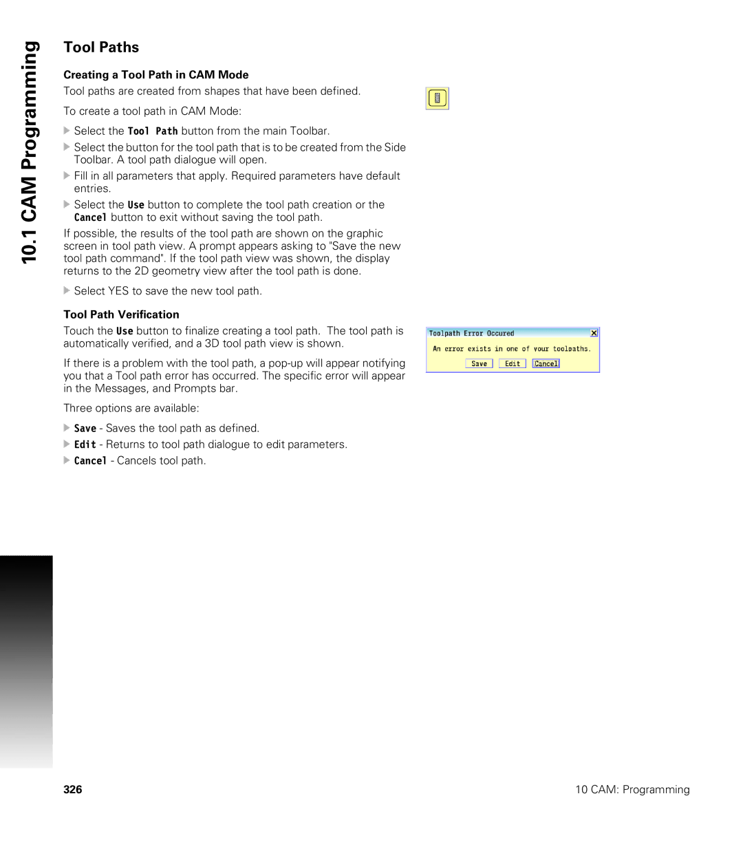
Tool Path Verification
Use Existing Shape
Tool Path Editing
327
Editing a Tool Path
Disabling, and Enabling Tool Paths
Deleting Tool Paths
Arranging Tool Paths Sequence
CAM Mode file types Program generated by CAM
10.1
Smart Programming
Files Created
CAM Example
Exercise One
331
Connecting the Geometry
333
334 CAM Programming
Creating the tool paths
335
336 CAM Programming
337
338 CAM Programming
Create Circle Geometry
Example Two
339
340 CAM Programming
Create Line Geometry
341
342 CAM Programming
Programming
343
344 CAM Programming
345
346 CAM Programming
347
348 CAM Programming
Code Edit, Help, & Advanced Features
Activating Edit Mode
Code Program Editing
351
When editing a program, the following buttons are available
Edit Features menu
353
354
355
Delete a Character
357
358
Overwriting Text
Inserting Text
359
360
Replace Specific Text, or Code in a program
361
Preview Features
Edit Help Preview
363
Code and M-Code Definitions
Code
Shifts the location of Absolute Zero to a preset location.
Contouring Mode OFF. Modal Exact Stop Check. Activates
In-Position Mode
Exact Stop Mode OFF. Modal Contouring Mode. De-activates
G80
End Mill Cycle
367
Code Definition
Typing in M-Codes
Typing in Address Words
369
Edit Help
Activating Edit Help
Help Graphic Screens
371
372
Multi -Segment Blocks
Basic Modal Functions
373
Arcs
Drilling Cycles
Milling and Profiles
Pocket Cycles
375
Rotation, Scaling, and Mirroring
Spindle Probing
Tool Radius Compensation
Tool Probing
377
Other G Functions
All M Functions
379
Cooling, Cleaning, and Lubrication
Basic M Functions
Tool Change
Spindle Functions
381
Code Function Spindle Speed Commands spindle speeds S
Advanced Programming
Miscellaneous M-Code
Code Function
Control M Codes
383
Order of Execution
In-Position Mode Exact Stop Check
Contouring Mode Cutting Mode
Programming Non-modal Exact Stop
385
Return from Reference Point
Setting Stroke Limit
Move Reference from Machine Datum
Modifiers
Block Separators
Modifier Function
387
Tool Offset Modification
Temporary Format T1 D.5500 L-1.1000
Block #
Tool Modification Programming Example
389
O1 * SUBPGM-1
Operators and Functions Expression
Expressions and Functions
391
Expression Function
Examples Ref. Example
393
394
Variable Description
System Variables
395
User Variables
Variable Programming Parametric
Block Skip
Example N11 #1000 = 1 *Note 0=OFF, 1=ON
397
Select Block Skip
Example N11 #1002 = 1 *Note 0=OFF, 1=ON
Parameters and Variable Registers
Contents of Variables Print
399
Setting and Direct Transfer Variables
Indirect Transfer
401
Storing Result of Computation
Variable Programming Examples
403
SET Loop Number 1 IN. DP
405
#111 = 0 * SET Side CUT Increment to
Format # Function
User Macros G65, G66, G67
407
Macro Body Structure
Setting and Passing Parameters
409
G65 Macro Programming, Main
O99 * WINDOW-MACRO-CALL
G65 Macro Programming, Macro sub-program
411
G66/G67 Macro Programming
O101 * SLOTCALL.G
SLOTMAC.G Program
413
11.4
Macro Programming Hole Milling Macro
415
X1.5 Y0 * Move to Hole Center G1 Z-.5 * Move Z to Depth
417
G64 * Contouring Mode IF#70 then * COUNTER-CLOCKWISE
419
Probe Move G31
Conditional Statements
421
If Goto
Unconditional Loop Repeat
423
Command Abbreviation
Short Form Addressing
Logical and Comparative Terms
Statement Symbol True/false Table
425
Inequality Operators Not
File Inclusion
427
TOOLCHNG.G
429
Four Axis Programming
Axis Type
Linear
Rotary
Programming Examples
Rotary Axis Programming Conventions
431
T1 *#3 Centerdrill
O1 * Groove
433
T1 * Special THD-TOOLS3500
Software Update
Procedure for updating the software
Software Update
Updating System Software
Off-Line Software
Off-Line Simulator
13.1 3500i Off-Line Software
System Requirements
Installation
Operation
Updating
439
440
Index
441
MDI
442
443
444
Page
770530-25 Ver 2014