Chapter 2: Connecting and Configuring Hardware
To connect a 16701B expander frame
To connect a 16701B expander frame
1Install your measurement modules in the 16701B expander frame. Module installation instructions are on page 42. For information on specific measurement modules go to:
Module Type | Page |
|
|
Logic Analyzer | 45 |
Oscilloscope | 71 |
Pattern Generator | 87 |
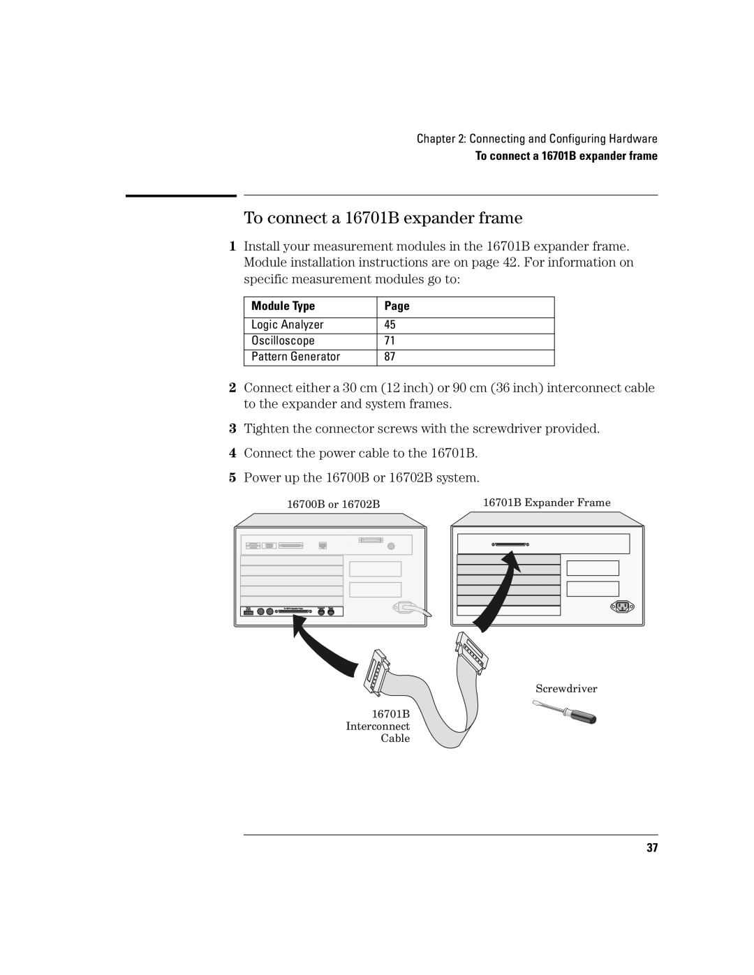
2Connect either a 30 cm (12 inch) or 90 cm (36 inch) interconnect cable to the expander and system frames.
3Tighten the connector screws with the screwdriver provided.
4Connect the power cable to the 16701B.
5Power up the 16700B or 16702B system.
|
| 16700B or 16702B | 16701B Expander Frame | ||||||||||
|
|
|
|
|
|
|
|
|
|
|
|
|
|
|
|
|
|
|
|
|
|
|
|
|
|
|
|
|
|
|
|
|
|
|
|
|
|
|
|
|
|
|
|
|
|
|
|
|
|
|
|
|
|
|
|
|
|
|
|
|
|
|
|
|
|
|
|
|
|
|
|
|
|
|
|
|
|
|
|
|
|
|
|
|
|
|
|
|
|
|
|
|
|
|
|
|
|
|
|
|
|
|
|
|
|
|
|
|
|
|
|
|
|
|
|
|
|
|
|
|
|
|
|
|
|
|
|
|
|
|
|
|
|
|
|
|
|
|
|
|
|
|
|
|
|
|
|
|
|
|
|
|
|
|
|
|
|
|
|
|
|
|
|
|
|
|
|
|
|
|
|
|
|
|
|
|
|
|
|
|
|
|
|
|
|
|
|
|
|
|
|
|
|
|
|
Screwdriver
16701B Interconnect Cable
37