NOTE:
NOTE:
Chapter 3: Installing Logic Analyzer Measurement Modules
16715/16/17A, 16718/19A, 16740/41/42A, 16750/51/52A/B Logic Analyzer
16715/16/17A, 16718/19A, 16740/41/42A, 16750/51/52A/B Logic Analyzer
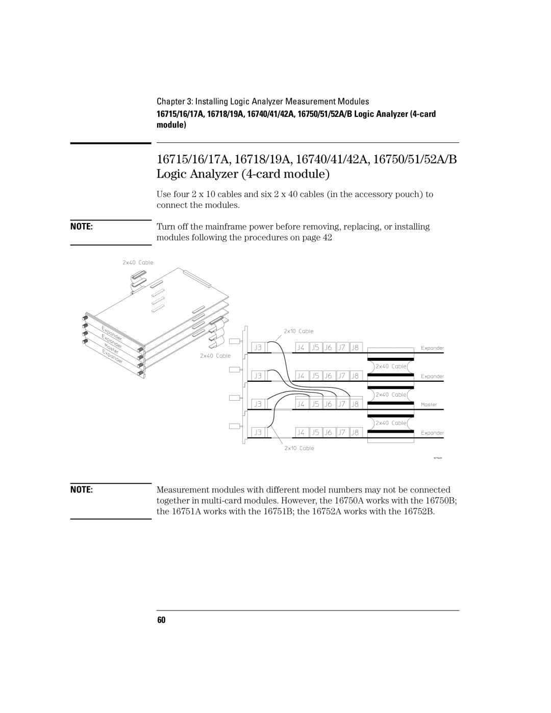
Use four 2 x 10 cables and six 2 x 40 cables (in the accessory pouch) to connect the modules.
Turn off the mainframe power before removing, replacing, or installing modules following the procedures on page 42
Measurement modules with different model numbers may not be connected together in
60