Chapter 3: Installing Logic Analyzer Measurement Modules
16710/11/12A Logic Analyzer
| 16710/11/12A Logic Analyzer |
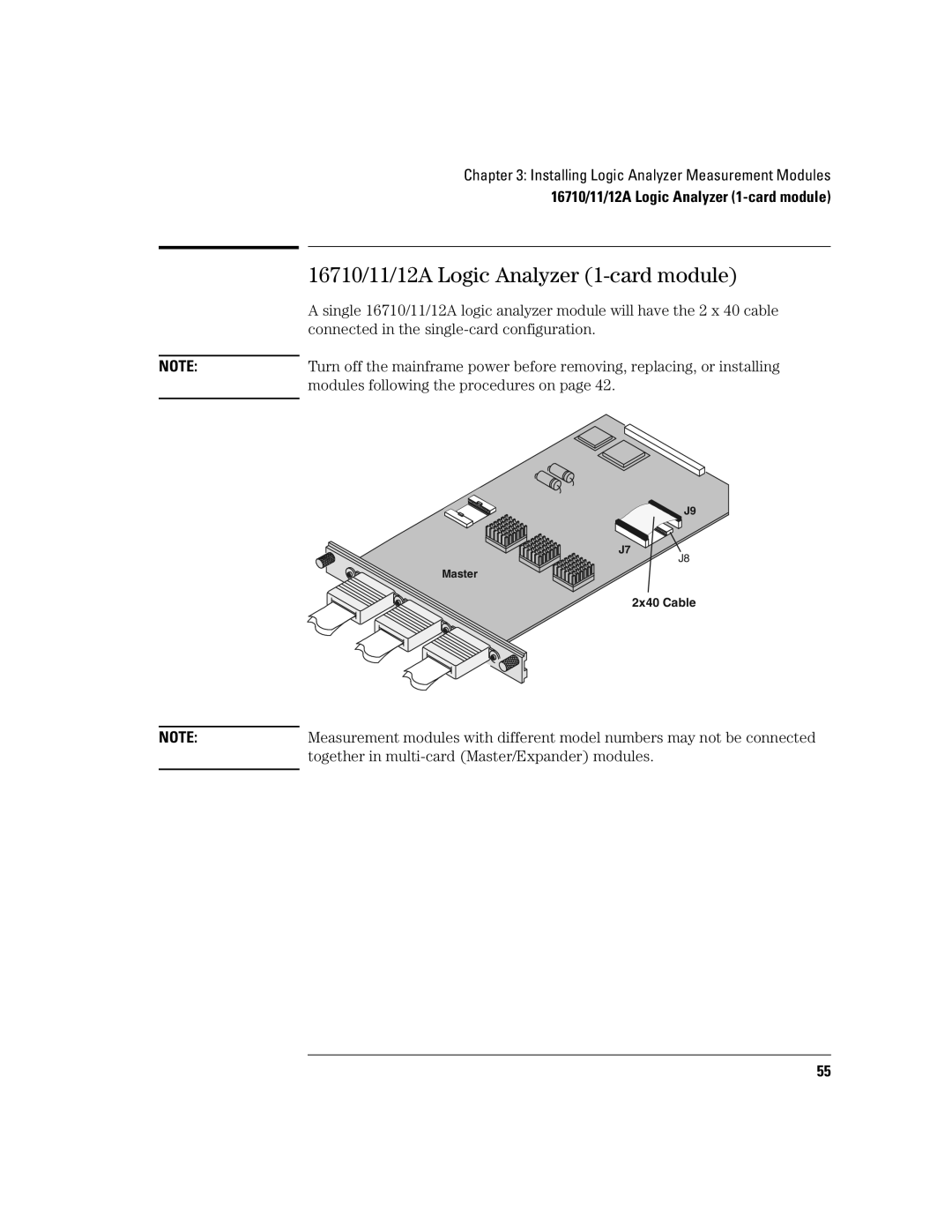
| A single 16710/11/12A logic analyzer module will have the 2 x 40 cable |
| connected in the |
|
|
NOTE: | Turn off the mainframe power before removing, replacing, or installing |
| modules following the procedures on page 42. |
|
|
![]() J9
J9
J7
J8
Master
2x40 Cable
NOTE: | Measurement modules with different model numbers may not be connected |
| together in |
|
|
55