Chapter 3: Installing Logic Analyzer Measurement Modules
16710/11/12A Logic Analyzer
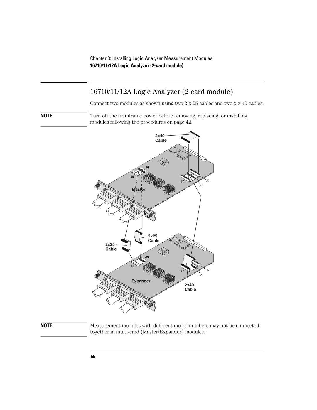
| 16710/11/12A Logic Analyzer |
| Connect two modules as shown using two 2 x 25 cables and two 2 x 40 cables. |
NOTE: | Turn off the mainframe power before removing, replacing, or installing |
| modules following the procedures on page 42. |
| 2x40 |
| Cable |
J6
J5
J7 | J9 |
J8
Master
2x25
Cable
2x25 Cable
J6
J5
J7J9
J8
Expander
2x40
Cable
NOTE: | Measurement modules with different model numbers may not be connected |
| together in |
|
|
56