NOTE:
CAUTION:
NOTE:
Chapter 6: Connecting Accessories
Direct connection
Direct connection
For all Agilent logic analyzers except 16517A, 16518A, 16760A, and 16753/54/55/56A.
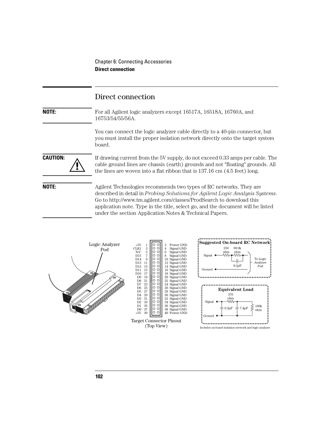
You can connect the logic analyzer cable directly to a
If drawing current from the 5V supply, do not exceed 0.33 amps per cable. The cable ground lines are chassis (earth) grounds and not "floating" grounds. All the lines are woven into a flat ribbon that is 137.16 cm (4.5 feet) long.
Agilent Technologies recommends two types of RC networks. They are described in detail in Probing Solutions for Agilent Logic Analysis Systems. Go to http://www.tm.agilent.com/classes/ProdSearch to download this application note. Type in the title, select go, and the document will be listed under the section Application Notes & Technical Papers.
Logic Analyzer | +5V | 1 | |
Pod | CLK1 | 3 | |
N/C | 5 | ||
| |||
| D15 | 7 | |
| D14 | 9 | |
| D13 | 11 | |
| D12 | 13 | |
| D11 | 15 | |
| D10 | 17 | |
| D9 | 19 | |
| D8 | 21 | |
| D7 | 23 | |
| D6 | 25 | |
| D5 | 27 | |
| D4 | 29 | |
| D3 | 31 | |
| D2 | 33 | |
| D1 | 35 | |
| D0 | 37 | |
| +5V | 39 |
2 | Power GND | Suggested | |||
250 | 90.9k |
| |||
4 | Signal GND |
| |||
6 | Signal GND | ohm | ohm |
| |
8 | Signal GND | Signal |
| To Logic | |
10 | Signal GND |
|
| ||
12 | Signal GND |
| 8.2pF | Analyzer | |
14 | Signal GND | Ground | Pod | ||
16 | Signal GND |
|
| ||
18 | Signal GND |
|
|
| |
20 | Signal GND |
|
|
| |
22 | Signal GND |
|
|
| |
24 | Signal GND |
|
|
| |
26 | Signal GND | Equivalent Load |
| ||
28 | Signal GND |
| |||
370 |
|
| |||
30 | Signal GND |
|
| ||
32 | Signal GND | ohm |
| ||
34 | Signal GND | Signal |
|
| |
36 | Signal GND | 0.3pF | 7.4pF | 100k | |
38 | Signal GND | ohm | |||
|
| ||||
40 | Power GND | Ground |
|
| |
|
|
|
| ||
Target Connector Pinout |
|
(Top View) | Includes |
|
102