OmniSwitch 6600 Family Chassis and Hardware Components | OmniSwitch |
|
|
|
|
Console Port |
|
| Gigabit Ethernet Uplink Module Slot |
|
| ||||
The | The | ||||||||
port for console connections. Serial console con- | uplink modules. This slot supports the following module types: | ||||||||
nections are used by network administrators for | • | ||||||||
switch management. This female | connections (uses two | ||||||||
provides a DCE console connection. |
| up to 100 meters. |
|
|
|
| |||
|
|
|
| • | |||||
|
|
|
| support | |||||
TM OmniSwitch |
|
|
|
|
|
|
| ||
|
| 1 3 5 7 | 9 11 13 15 | 17 19 21 | 23 |
| EXPANSION | EXPANSION/STACKING | |
|
|
|
|
|
| 25 | 26 | 2 7 | 2 8 |
| CONSOLE |
|
|
|
|
|
|
|
|
|
| SEL |
|
|
|
|
|
|
|
OK1 | PS1 | 2 |
|
| 24 |
|
|
|
|
|
|
|
|
|
|
|
| LINK/ACT | LINK/ACT |
OK2 | PS2 PRI SEC FAN TEMP | 1 | 2 | 3 | 4 | 5 | 6 | 7 | 8 | 9 | 10 | 11 | 12 | 13 | 14 | 15 | 16 | 17 | 18 | 19 | 20 | 21 | 22 | 23 | 24 |
Status and Slot Indicator LEDs
For information on the
Slot Selector Button
The slot selector button, located directly beneath the slot indicator LED, is used to manually assign slot numbers to switches in stacked configurations. Refer to Chapter 4, “Managing OmniSwitch 6600 Family Stacks,” for detailed infor- mation.
100 Fiber Ethernet SFP Ports The
Stacking or Uplink Module Slot
The
If you use a Gigabit Ethernet uplink module in this slot, the
A stacking module must be installed in this slot if the switch is to be used in a stack. For detailed information on stacking switches, refer to Chapter 4, “Managing OmniSwitch 6600 Family Stacks.”
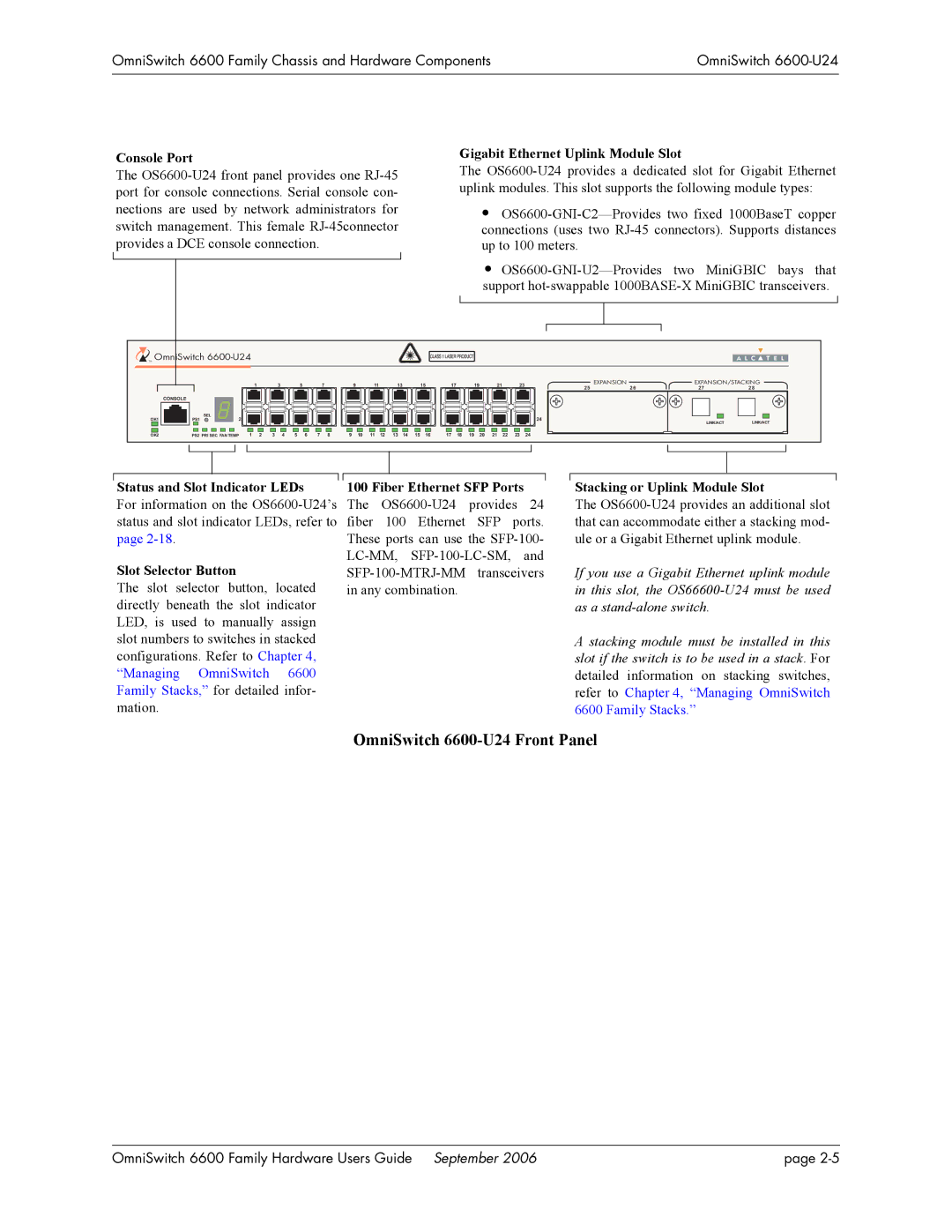
OmniSwitch 6600-U24 Front Panel
OmniSwitch 6600 Family Hardware Users Guide September 2006 | page |