Managing OmniSwitch 6600 Family Stacks | Setting Up a Stacked Configuration |
|
|
|
|
Redundant Stack Connection
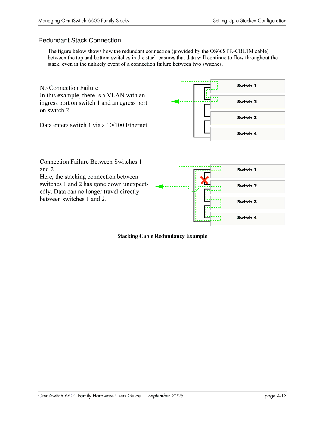
The figure below shows how the redundant connection (provided by the OS66STK-CBL1M cable) between the top and bottom switches in the stack ensures that data will continue to flow throughout the stack, even in the unlikely event of a connection failure between two switches.
No Connection Failure
In this example, there is a VLAN with an ingress port on switch 1 and an egress port on switch 2.
Data enters switch 1 via a 10/100 Ethernet
Connection Failure Between Switches 1 and 2
Here, the stacking connection between switches 1 and 2 has gone down unexpect- edly. Data can no longer travel directly between switches 1 and 2.
Switch 1
Switch 2
Switch 3
Switch 4
Switch 1
Switch 2
Switch 3
Switch 4
Stacking Cable Redundancy Example
OmniSwitch 6600 Family Hardware Users Guide September 2006 | page |