Chapter 4: Installing the Power Supplies
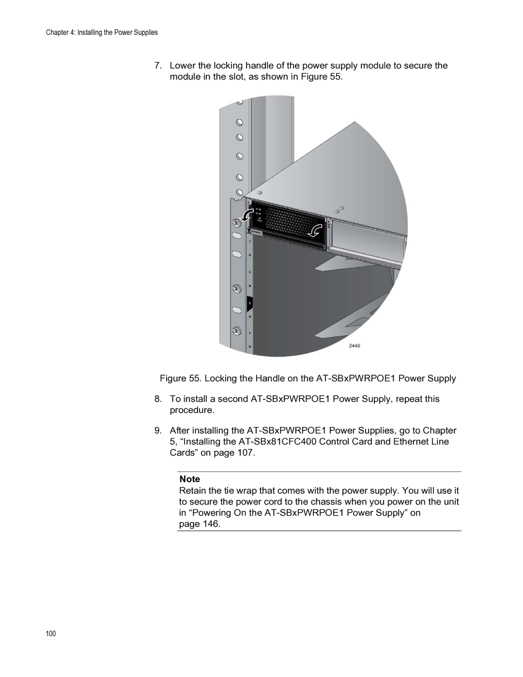
7.Lower the locking handle of the power supply module to secure the module in the slot, as shown in Figure 55.
Figure 55. Locking the Handle on the AT-SBxPWRPOE1 Power Supply
8.To install a second AT-SBxPWRPOE1 Power Supply, repeat this procedure.
9.After installing the AT-SBxPWRPOE1 Power Supplies, go to Chapter 5, “Installing the AT-SBx81CFC400 Control Card and Ethernet Line Cards” on page 107.
Note
Retain the tie wrap that comes with the power supply. You will use it to secure the power cord to the chassis when you power on the unit in “Powering On the AT-SBxPWRPOE1 Power Supply” on
page 146.