Chapter 4: Installing the Power Supplies
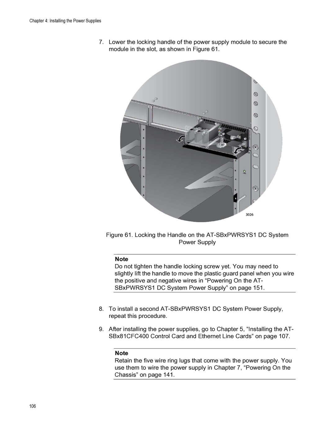
7.Lower the locking handle of the power supply module to secure the module in the slot, as shown in Figure 61.
Figure 61. Locking the Handle on the AT-SBxPWRSYS1 DC System
Power Supply
Note
Do not tighten the handle locking screw yet. You may need to slightly lift the handle to move the plastic guard panel when you wire the positive and negative wires in “Powering On the AT- SBxPWRSYS1 DC System Power Supply” on page 151.
8.To install a second AT-SBxPWRSYS1 DC System Power Supply, repeat this procedure.
9.After installing the power supplies, go to Chapter 5, “Installing the AT- SBx81CFC400 Control Card and Ethernet Line Cards” on page 107.
Note