Chapter 1: Overview
Power Supply Interfaces (Opto-couplers)
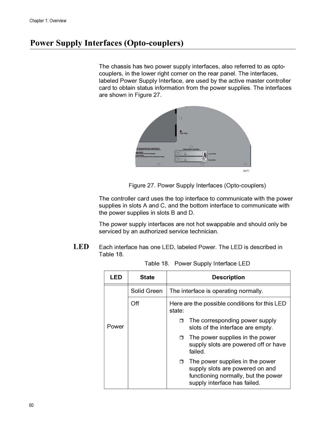
The chassis has two power supply interfaces, also referred to as opto- couplers, in the lower right corner on the rear panel. The interfaces, labeled Power Supply Interface, are used by the active master controller card to obtain status information from the power supplies. The interfaces are shown in Figure 27.
Figure 27. Power Supply Interfaces (Opto-couplers)
The controller card uses the top interface to communicate with the power supplies in slots A and C, and the bottom interface to communicate with the power supplies in slots B and D.
The power supply interfaces are not hot swappable and should only be serviced by an authorized service technician.
LED Each interface has one LED, labeled Power. The LED is described in Table 18.
Table 18. Power Supply Interface LED
LED | State | Description |
|
|
|
|
|
|
| Solid Green | The interface is operating normally. |
|
|
|
| Off | Here are the possible conditions for this LED |
|
| state: |
Power |
| The corresponding power supply |
| slots of the interface are empty. | |
|
| The power supplies in the power |
|
| supply slots are powered off or have |
|
| failed. |
|
| The power supplies in the power |
|
| supply slots are powered on and |
|
| functioning normally, but the power |
|
| supply interface has failed. |
|
|
|
60