Chapter 4: Installing the Power Supplies
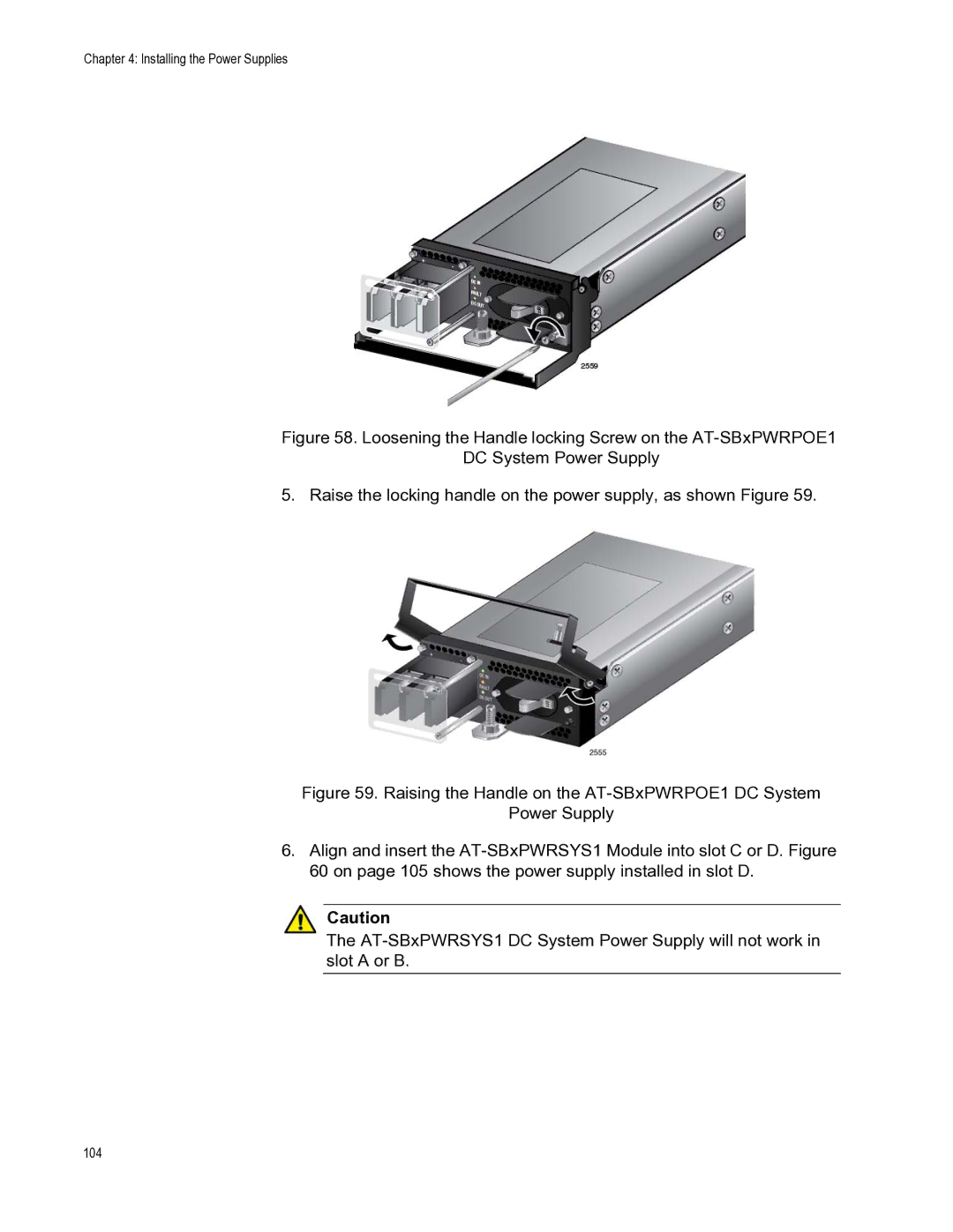
Figure 58. Loosening the Handle locking Screw on the AT-SBxPWRPOE1
DC System Power Supply
5. Raise the locking handle on the power supply, as shown Figure 59.
Figure 59. Raising the Handle on the AT-SBxPWRPOE1 DC System
Power Supply
6.Align and insert the AT-SBxPWRSYS1 Module into slot C or D. Figure 60 on page 105 shows the power supply installed in slot D.
Caution