SwitchBlade x8112 Chassis Switch Installation Guide
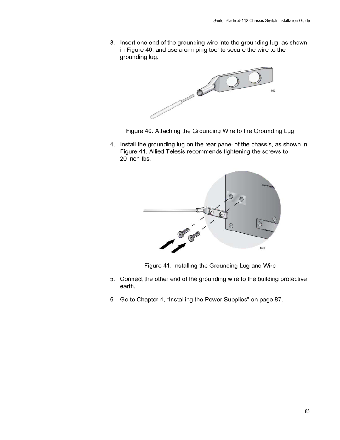
3.Insert one end of the grounding wire into the grounding lug, as shown in Figure 40, and use a crimping tool to secure the wire to the grounding lug.
Figure 40. Attaching the Grounding Wire to the Grounding Lug
4.Install the grounding lug on the rear panel of the chassis, as shown in Figure 41. Allied Telesis recommends tightening the screws to
20 inch-lbs.
Figure 41. Installing the Grounding Lug and Wire
5.Connect the other end of the grounding wire to the building protective earth.
6.Go to Chapter 4, “Installing the Power Supplies” on page 87.
85