Chapter 1: Overview
Note
To avoid installing both AC and DC power supplies in the same chassis, you should use the
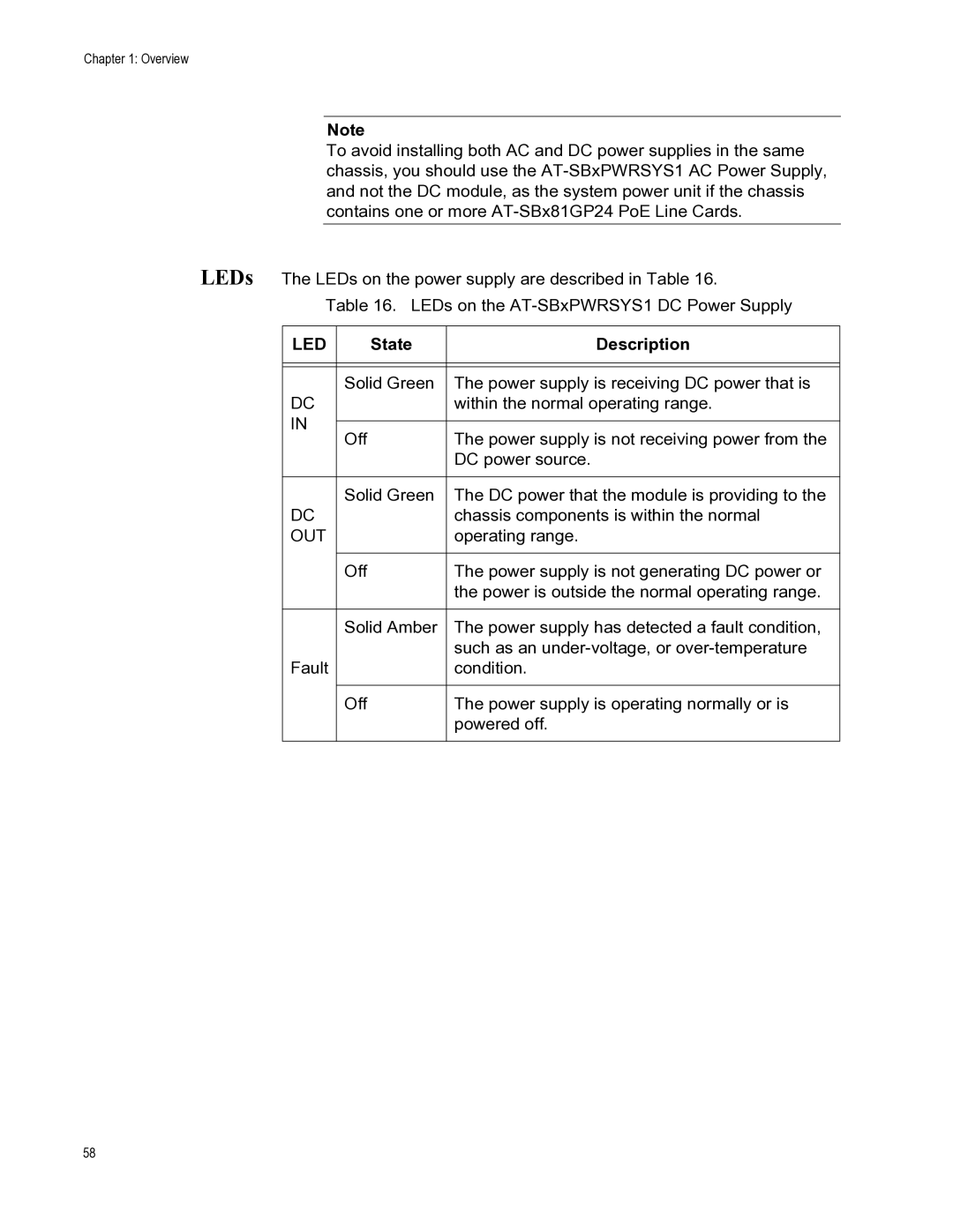
LEDs The LEDs on the power supply are described in Table 16.
Table 16. LEDs on the
LED | State | Description | |
|
|
| |
|
|
| |
| Solid Green | The power supply is receiving DC power that is | |
DC |
| within the normal operating range. | |
IN |
|
| |
Off | The power supply is not receiving power from the | ||
| |||
|
| DC power source. | |
|
|
| |
| Solid Green | The DC power that the module is providing to the | |
DC |
| chassis components is within the normal | |
OUT |
| operating range. | |
|
|
| |
| Off | The power supply is not generating DC power or | |
|
| the power is outside the normal operating range. | |
|
|
| |
| Solid Amber | The power supply has detected a fault condition, | |
|
| such as an | |
Fault |
| condition. | |
|
|
| |
| Off | The power supply is operating normally or is | |
|
| powered off. | |
|
|
|
58