Chapter 3: Installing the Chassis in an Equipment Rack
Unpacking the AT-SBx8112 Chassis
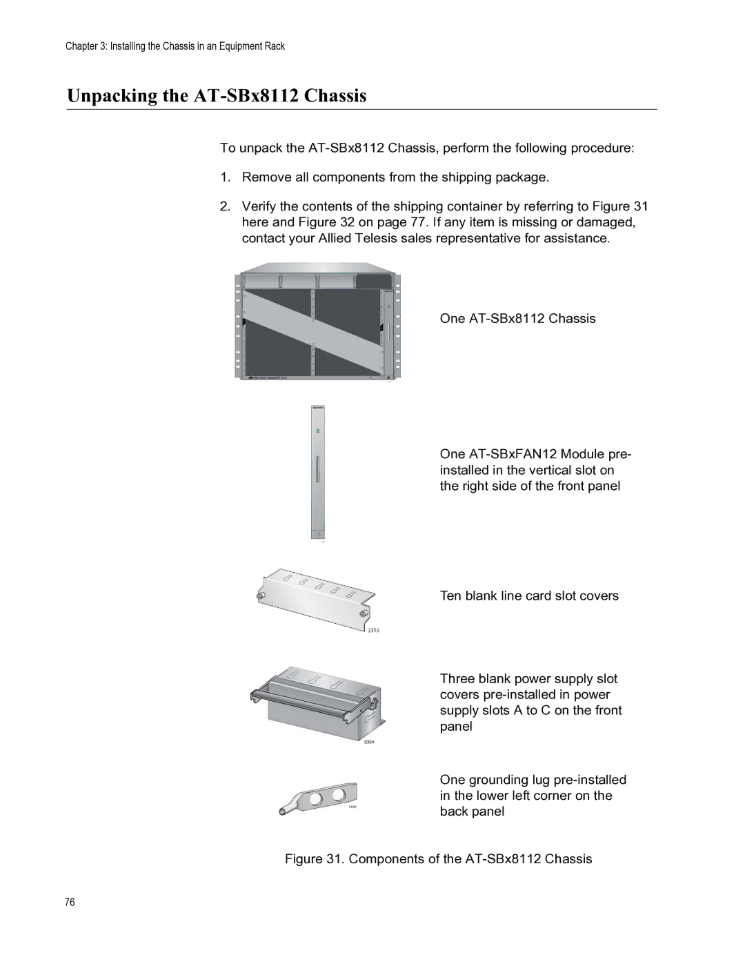
To unpack the
1.Remove all components from the shipping package.
2.Verify the contents of the shipping container by referring to Figure 31 here and Figure 32 on page 77. If any item is missing or damaged, contact your Allied Telesis sales representative for assistance.
One
One
Ten blank line card slot covers
Three blank power supply slot covers
One grounding lug
Figure 31. Components of the AT-SBx8112 Chassis
76