Chapter 3: Installing the Chassis in an Equipment Rack
Adjusting the Equipment Rack Brackets
You may set the position of the chassis relative to the front of the equipment rack by adjusting the two equipment rack brackets that are pre- installed on the sides of the unit. The front of the chassis can be flush with, extend beyond, or be recessed behind the front of the equipment rack. You may also install the chassis so that the rear panel is flush with the front of the equipment rack.
The different bracket positions are listed in Table 20 and illustrated in Figure 33 on page 79 and Figure 34 on page 79. Please review the following information before moving the brackets:
Position A, the default position, positions the chassis so that the front of the unit is flush with the front of the equipment rack.
Position B recesses the front of the chassis by 27.39 mm (1.1 in).
Positions C to E extend the front of the chassis beyond the front of the rack from 27.39 mm (1.1 in) to 140.85 mm (5.545 in).
Position F installs the chassis with the rear panel flush with the front of the equipment rack.
To install the rack mount brackets in position “E,” you have to remove the two chassis screws from the
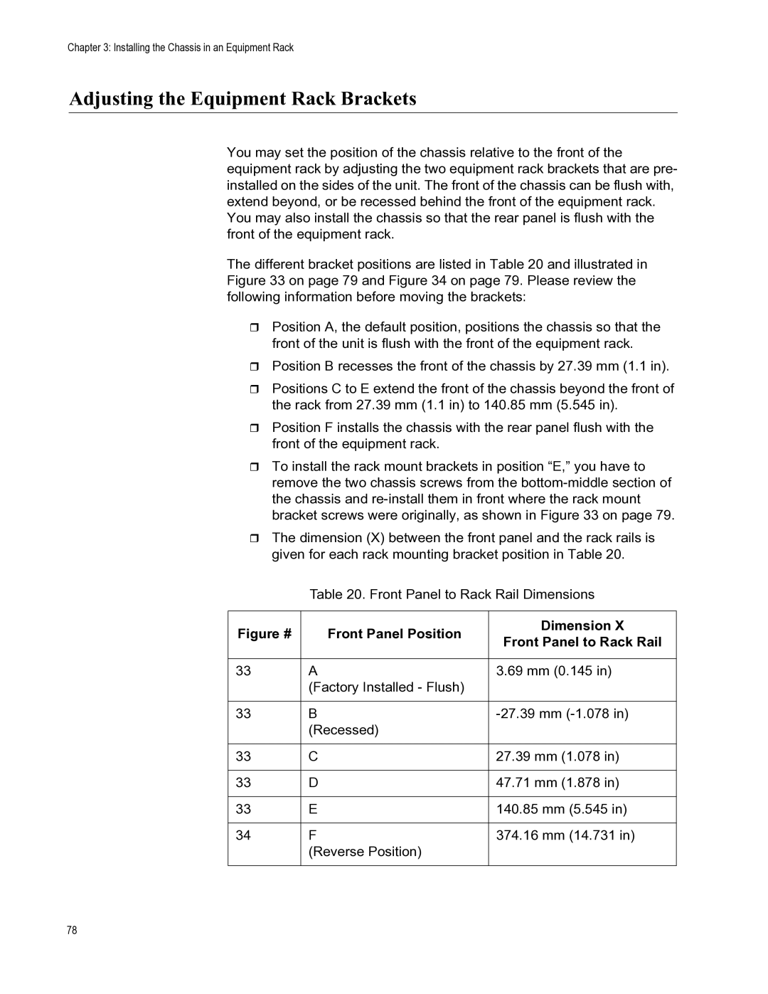
The dimension (X) between the front panel and the rack rails is given for each rack mounting bracket position in Table 20.
Table 20. Front Panel to Rack Rail Dimensions
Figure # | Front Panel Position | Dimension X | |
Front Panel to Rack Rail | |||
|
| ||
|
|
| |
33 | A | 3.69 mm (0.145 in) | |
| (Factory Installed - Flush) |
| |
|
|
| |
33 | B | ||
| (Recessed) |
| |
|
|
| |
33 | C | 27.39 mm (1.078 in) | |
|
|
| |
33 | D | 47.71 mm (1.878 in) | |
|
|
| |
33 | E | 140.85 mm (5.545 in) | |
|
|
| |
34 | F | 374.16 mm (14.731 in) | |
| (Reverse Position) |
| |
|
|
|
78