Modes
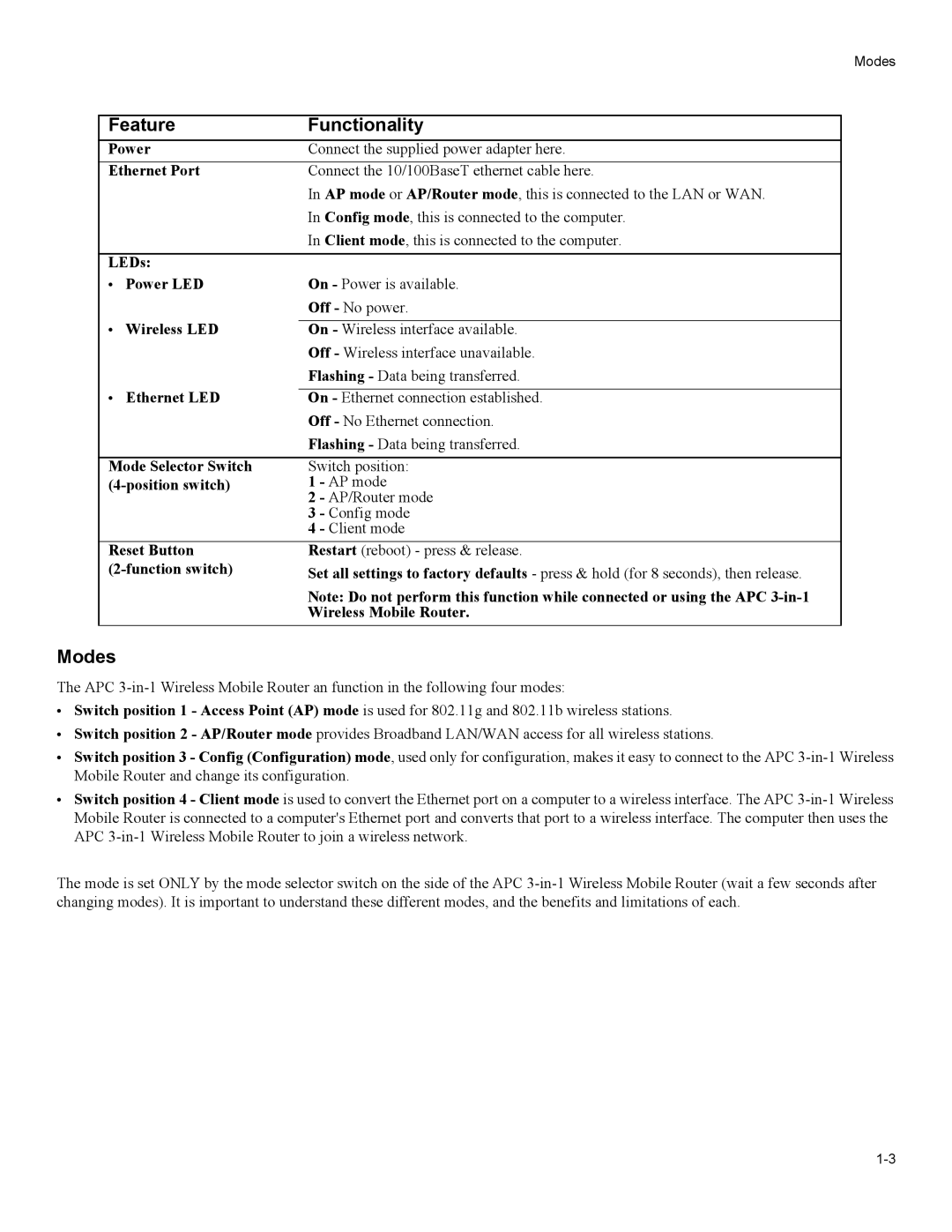
Feature | Functionality | |
Power | Connect the supplied power adapter here. | |
Ethernet Port | Connect the 10/100BaseT ethernet cable here. | |
|
| In AP mode or AP/Router mode, this is connected to the LAN or WAN. |
|
| In Config mode, this is connected to the computer. |
|
| In Client mode, this is connected to the computer. |
|
| |
LEDs: |
| |
• | Power LED | On - Power is available. |
|
| Off - No power. |
• | Wireless LED |
|
On - Wireless interface available. | ||
|
| Off - Wireless interface unavailable. |
|
| Flashing - Data being transferred. |
• | Ethernet LED |
|
On - Ethernet connection established. | ||
|
| Off - No Ethernet connection. |
|
| Flashing - Data being transferred. |
|
| |
Mode Selector Switch | Switch position: | |
1 - AP mode | ||
|
| 2 - AP/Router mode |
|
| 3 - Config mode |
|
| 4 - Client mode |
Reset Button | Restart (reboot) - press & release. | |
Set all settings to factory defaults - press & hold (for 8 seconds), then release. | ||
Note: Do not perform this function while connected or using the APC
Wireless Mobile Router.
Modes
The APC
•Switch position 1 - Access Point (AP) mode is used for 802.11g and 802.11b wireless stations.
•Switch position 2 - AP/Router mode provides Broadband LAN/WAN access for all wireless stations.
•Switch position 3 - Config (Configuration) mode, used only for configuration, makes it easy to connect to the APC
•Switch position 4 - Client mode is used to convert the Ethernet port on a computer to a wireless interface. The APC
The mode is set ONLY by the mode selector switch on the side of the APC