Chapter 1 Overview
Hardware Features
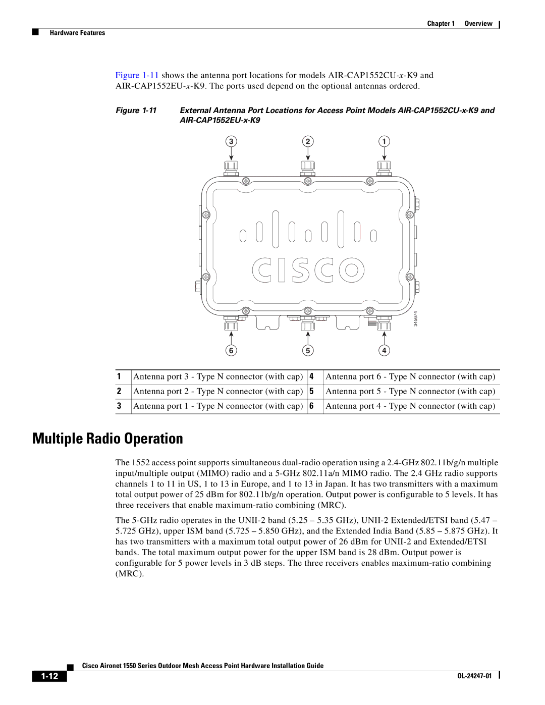
Figure 1-11 shows the antenna port locations for models AIR-CAP1552CU-x-K9 and
AIR-CAP1552EU-x-K9. The ports used depend on the optional antennas ordered.
Figure 1-11 External Antenna Port Locations for Access Point Models AIR-CAP1552CU-x-K9 and AIR-CAP1552EU-x-K9
3 | 2 | 1 |
|
|
| 345674 |
| 6 | 5 | 4 |
1 | Antenna port 3 - Type N connector (with cap) | 4 | Antenna port 6 - Type N connector (with cap) |
2 | Antenna port 2 - Type N connector (with cap) | 5 | Antenna port 5 - Type N connector (with cap) |
3 | Antenna port 1 - Type N connector (with cap) | 6 | Antenna port 4 - Type N connector (with cap) |
Multiple Radio Operation
The 1552 access point supports simultaneous
The
| Cisco Aironet 1550 Series Outdoor Mesh Access Point Hardware Installation Guide |