Release May
Cisco BPX 8600 Series Reference
Page
Page
Page
Chapter Introduction
About This Manual
Chapter General Description
BPX Switch Common Core
Chapter Network Interface Trunk Cards
Chapter Service Interface Line Cards
BXM T3/E3, 155,
Simba
Chapter ATM Connections
Chapter ATM and Frame Relay SVCs SPVCs
Chapter Tag Switching
Chapter BME Multicasting
Chapter Repair and Replacement 11-1
Chapter Tiered Networks 13-1
Chapter Frame Relay to ATM Network Service Interworking 12-1
Chapter BPX Snmp Agent 14-1
Appendix a BPX Node Specifications
Appendix B BPX Switch Cabling Summary
Appendix C BPX Switch Peripherals
Appendix E Glossary Index
Appendix D AT3-6ME Interface Adapter
F I G U R E S
Xviii Cisco BPX 8600 Series Reference
List of Figures
Dial-Modem Cabling for Auto Answer Dial-In to BPX
T a B L E S
Table B-1
Table A-1
Table B-2
Table B-3
Table C-2
Table C-1
Table C-3
Table C-4
Xxiv Cisco BPX 8600 Series Reference
About This Manual
Cisco WAN Switching Product Name Change
Objectives
Audience
Organization
Chapter Repair and Replacement
Chapter Tag Switching
Chapter Frame Relay to ATM Network and Service Interworking
Appendix a BPX Node Specifications
Related Documentation
Conventions
Related Documentation
Conventions
Xxx Cisco BPX 8600 Series Reference
Introduction
General Description
BPX Capabilities
General Description BPX Switch General Configuration Example
Extended Services Processor
BPX Switch
Continuing Features with Release
MGX IGX Switch
New with Release
Network
Continuing Features with Release
IMATM-B
Access Products
BPX Switch Operation
BPX Switch Operation
BPX Switch Operation
Tag Switching
BPX Switch with MGX 8220 Shelves
BPX Switch with Extended Services Processor
Frame Relay to ATM Interworking
Frame Relay to ATM Network Interworking
Service Interworking
Tiered Networks
Additional Information
Routing Hubs and Interface Shelves
BPX Switch Routing Hubs
Inverse Multiplexing ATM
Tiered Network with BPX Switch and IGX Switch Routing Hubs
Virtual Trunking Example
Virtual Trunking
Traffic and Congestion Management
FairShare
Traffic and Congestion Management
OptiClass
AutoRoute
Cost-Based AutoRoute
Congestion Management, ForeSight
Congestion Management, VS/VD
Network Management
Network Interfaces
Network Management
Service Interfaces
Statistical Alarms and Network Statistics
Node Synchronization
Switch Software Description
Switch Software Description
Connections and Connection Routing
Connection Routing Groups
Cost-Based Connection Routing
Major Features of Cost-Based AutoRoute
22Cisco BPX 8600 Series Reference
Cost-Based AutoRoute Commands
Network Synchronization
Network Synchronization
Node Alarms
Switch Availability
Switch Availability
Node Redundancy
Switch Availability
26Cisco BPX 8600 Series Reference
BPX Switch Enclosure
General Description
Physical Description
Physical Description
BPX Switch Exterior Front View
Node Cooling
Node DC Powering
DC Power Entry Module Shown with Conduit Box Removed
Optional AC Power Supply Assembly
AC Power Supply Assembly Front View
Card Shelf Configuration
BPX Switch Card Shelf Front View
Physical Layer
Functional Description
ATM Layer
Functional Description
ATM Cell Format
ATM Cell Headers
NNI Header
Functional Description UNI Header
Functional Description STI Header
STI Header
ATM Adaptation Layer
ATM Cell Addressing
AAL
Smds
11 SAR Adaptation Process
IPX and IGX Switch Trunk Interfaces to ATM
BAM
STI
FastPacket Adaptation to ATM
CAM UNI
SAM UNI
Simple Gateway
Complex Gateway, Frame Relay to ATM Network Interworking
Simple and Complex Gateway Formats
BPX Switch Major Groups
BPX Switch Major Groups
BPX Switch Plug-In Card Summary Card Name Where
Smfxlr
BME
LM-2OC3-SMF
LM-2OC3-SMFLR
Optional Peripherals
Optional Peripherals
BPX Switch Common Core Group
BPX Switch Common Core
Common Core Group Block Diagram
Broadband Controller Card BCC-32, BCC-3, BCC-4
Broadband Controller Card BCC-32, BCC-3, BCC-4
Features
Functional Description
BCC-32 and BCC-3 Block Diagram
Indicator Function
BCC Front Panel Indicators
Front Panel Description
LAN
BCC Front Panel
Card
Back Cards for the BCC-3 and BCC-32
Gbps Operation with the BCC-4
Enter y
Step
Connector Function
Backcard Line Module for BCC-32, Connectors
EXT 2 TMG
EXT 1 TMG
BCC-3-bc or BCC-c Face Plate Connectors
Alarm/Status Monitor Card
Alarm/Status Monitor Card
Controls Indicator Function
ASM Front Panel Controls and Indicators
ACO
Status
Line Module for the Alarm/Status Monitor Card
LM-ASM Face Plate Connectors
Connector Indicator Function
LMI-ASM Face Plate
BPX Switch StrataBus 9.6 and 19.2 Gbps Backplanes
BPX Switch StrataBus 9.6 and 19.2 Gbps Backplanes
18Cisco BPX 8600 Series Reference
BPX Switch Network Interface Group
BXM Cards, Trunk Mode Summary
Network Interface Trunk Cards
Broadband Network Interface Cards BNI-T3 and BNI-E3
Broadband Network Interface Cards BNI-T3 and BNI-E3
Egress
Ingress
Simplified BNI-T3, BNI-E3 Block Diagram
Bandwidth Control
Loopbacks and Diagnostics
Front Panel Indicators
BNI Front Panel Status Indicators
Status LED color Status Description
Status port
T3 and E3 Line Modules LM-3T3 and LM-3E3
LM-3T3 and LM-3E3 Connectors
Port 1 RX TX
Port 2 RX TX
LM-3T3 Face Plate, Typical
T3 and E3 Line Modules LM-3T3 and LM-3E3
LM-3E3 Face Plate, Typica
Overview
Broadband Network Interface Cards, BNI-155
Egress
Ingress
CBR VBR
Simplified BNI-155 Block Diagram
Act Stby Fail Failure Description
7BNI-155 Front Panel
LM-OC3-MMF Connectors Function
LM-OC3-SMF and LM-OC3-SMFLR Connectors Function
OC3, Line Modules SMF, SMFLR, & MMF
OC3, Line Modules SMF, SMFLR, & MMF
LM-2OC3-SMF Face Plate
LM-2OC3-MMF Face Plate
Cabling of BNI Backcard, SMF-2-BC
Cabling of BNI Backcard, SMF-2-BC
20Cisco BPX 8600 Series Reference
Service Interface Line Cards
BPX Switch Service Interface Group Summary
BXM Cards, Port UNI Mode Summary
ASI-1, ATM Service Interface Card
ASI-1, ATM Service Interface Card
Egress
Configuring Connections ATM over ASI Example
Monitoring Statistics
6Cisco BPX 8600 Series Reference
ASI-1 Front Panel
LM-2T3 Module
LM-2T3 Module
Line Module, ASI, 2T3
LM-2E3 Module
LM-2E3 Module
Line Module, ASI, 2E3
ASI-155, ATM Service Interface Card
ASI-155, ATM Service Interface Card
Configuring Connections
ASI-155 Simplified Block Diagram
Service Interface Line Cards
ASI-155 Front Panel
ASI-155 Line Module, LM-2OC3-SMF
BXM Cards, Access UNI Mode
ASI-155 Line Module, LM-2OC3-SMFLR
ASI-155 Line Module, LM-2OC3-MMF
BXM Cards, Access UNI Mode
BXM T3/E3, 155,
Tag Switching
Dynamic Resource Partitioning for SPVCs
BXM Cards
Dynamic Resource Partitioning for SPVCs
BXM Cards
OC3/STM-1 155.52 Mbps
T3/E3 45 Mbps/34Mbps
OC12/STM-4 622.08 Mbps
BPX-T3/E3-BC
BXM Capabilities
Features
T3/E3 45 Mbps/34 Mbps
OC3/STM-1 155.520 Mbps
BXM Capabilities
ATM Layer
CBR Service
Service Types
VBR Service
ABR Service
BXM Front Panel Status Indicators
BXM Front Card Indicators
BXM Front Panel Card Failure indicators
Card Operation
Card
BXM-155 Front Panel, Eight-Port Card Shown
BXM-T3/E3 Front Panel, 12-Port Card Shown
BXM-622 Backcards
BXM, Backcard Connectors
BXM-155 Backcards
BXM-T3/E3 Backcards
SMF-622-2, SMFLR-622-2, and SMFXLR-622-2 Back Card
BXM-155-8 Port Backcard, MMF, SMF, or Smflr
BPX-T3/E3 Back Card, 12-Port Option Shown
Y-Cabling of SMF-622 Series Backcards
Cabling of SMF-622 Series Backcards
Overview, Port UNI Mode
BXM Functional Description
BXM Functional Description
BXM Port Access UNI Ingress Operation
10 BXM Port Access, UNI Egress Operation
BXM Trunk Ingress Operation
Overview, Trunk Mode
BXM Trunk Egress Operation
DeMux/Mux
Detailed Description, Port UNI and Trunk Modes
ACP Subsystem Processor
Ingress and Egress Queue Engines
Fault Management and Statistics, Port UNI Mode
Fault Management and Statistics
Alarms
Performance Monitoring
Fault Management and Statistics, Trunk Mode
Technical Specifications
Technical Specifications
Physical Layer
General Information
General Sonet Notes
General Sonet Notes
Sonet Section, Line, and Path Descriptions
Unit Description
Diagnostics
User Commands
Connection Provisioning
Test
Configuration Management
Configuring Connections
Configuring Connections
Syntax
Configuring Connections Field Value Description
Command Line Interface Examples
Command Line Interface Examples
An example of the addtrk command follows
An example of the cnfln command follows
An example of the cnfportq command follows
An example of the upport command follows
An example of the cnfcls command for class 2 follows
YourID1 BPX Jan 1998 0241 GMT
An example of the cnfabrparm command follows
An example of the dsplns command follows
40Cisco BPX 8600 Series Reference
Dynamic Resource Partitioning for SPVCs
Resource Partitioning
Summary
Resource Partitioning
ASI SVC Resource Partitioning
Shown in the following example Example ASI cnfportq Command
BXM SVC Resource Partitioning
Example BXM cnfport Command
NNI Trunk SVC Resource Partitioning
TS,NTS,FR,FST,CBR,VBR,ABR
BNI Trunk SVC Resource Partitioning
BXM Trunk SVC Resource Partitioning
Example BNI cnftrkparm Command
Example BXM cnftrk Command
ATM Connections
ATM Connection Services
SVCs
SVCs
Traffic Parameters
Traffic Management Overview
QoS Parameters
Other Attributes
Standard ABR notes
Vsvd Description
BXM Connections
ATM Connection Requirements
ForeSight Congestion Control
ATM Connection Requirements
Addcon Command Syntax
Connection Routing
Field Value Description
ATM Connection Configuration
ATM Connection Configuration
SCR Flow
CLP0+1
BXM T3/E3, OC3
Default Setting OC12 Range ASI T3/E3 Range ASI-155 Range
ICR
RIF
RDF
Cdvt
PCR
Vsvd
SCR
IBS
CBR Policing Definitions ATM Forum TM Spec PCR Flow
CBR Connections
VBR Connections
VBR and Atfr Connections
Atfr Connections
Atfr Connection Prompt Sequence
ABR Notes
ABR and Atfst Connections
ABR Connections
ABR Standard Connection Prompt Sequence
Meaning of Vsvd and Flow Control External Segments
ABR ForeSight Connection Prompt Sequence
Atfst Connections
Atfst Connection Prompt Sequence
UBR Policing Definitions ATM Forum TM Spec PCR Flow
UBR Connections
Dual-Leaky Bucket An Analogy
Traffic Policing Examples
CBR Traffic Policing Examples
Traffic Policing Examples
11 CBR Connection, UPC Overview
12 CBR.1 Connection with Bucket Compliant
LP=1
VBR.1
VBR Dual-Leaky Bucket Policing Examples
14 VBR Connection, UPC Overview
Leaky Bucket
15 VBR Connection, Policing = 4, Leaky Bucket 1 Compliant
Examples
CLP=0
VBR.2
18 VBR.2 Connection, Leaky Bucket 2 Discarding CLP 0 Cells
LP=0
VBR.1
VBR.3
UBR Connection Policing
ABR Connection Policing
21 UBR Connection, UPC Overview
Configuration
Traffic Shaping for CBR, VBR, and UBR
Traffic Shaping for CBR, VBR, and UBR
Traffic Shaping Rates
LMI and Ilmi Parameters
ATM and Frame Relay SVCs and SPVCs
ATM and Frame Relay SVCs, and SPVCs
PVCs
PVCs and SVCs
SPVCs
ATM and Frame Relay SVCs and SPVCs
SVCs
BPX Switch and ESP Interfaces
Interim Inter-switch Protocol Routing
BPX Switch and ESP Interfaces
Signaling Plane
UNI Signaling Channel
Signaling Plane
UNI Signaling Channels
NNI Signaling Channel
Network Interworking Between Frame Relay and ATM
Network Interworking Between Frame Relay and ATM
Extended Services Processor
Extended Services Processor
ESP Interfaces
Redundant ESPs
Stand-Alone ESP
ESP Y-Cable Redundancy
Cable Redundancy
Other Redundancy Options
Resource Partitioning
Introduction
Tag Switching
Tag Switching Benefits
Tag Switching Overview
Tag Switching Benefits
Tag Switching Operation at Layer
Elements in a Tag Switching Network
Elements in a Tag Switching Network
Forwarding
Tag Switching in an ATM WAN
Tag Switching in an ATM WAN
Control
Tag Forwarding Information Base Tfib in an ATM Environment
Downstream on Demand Tag Allocation, Conservative Mode Shown
Tag Switching and the BPX
Tag Switching and the BPX
BPX Tag Switching
BPX Switch VSI Interfaces
Virtual Switch Interfaces
Connection Setup, End Points on same VSI Slave
Tag Switching Resource Configuration Parameters
Tag Switching Resource Configuration Parameters
Configuring VSI Lcns
Useful Default Allocations
Port VSI Partition LCN Allocation Elements
Details of More Rigorous Allocations
Requirements
List of Terms
Requirements
Configuration Management
Related Documents
Related Documents
Cnfqbin Command
Configuration Criteria
Cnfrsrc Command
Configuration Criteria
Example Parameter cnfrsrc Value Description
Cnfrsrc Parameter Summary
Resetcd 4 h
Configuration Example
Configuration Example
Dspcds
Status Active Revision CD18
Uptrk 4.1 uptrk 4.2 uptrk
Max PVC bandwidth Partition Enabled e VSI min LCNs
Cnfrsrc
VSI start VPI VSI end VPI VSI min b/w VSI max b/w
22Cisco BPX 8600 Series Reference
Cnfqbin 4.1 Enable/disable e
Dspqbin 4.1
Cnfqbin 4.1 10 e 0 65536 95 100
Addshelf 4.1 vsi 1
Checking and Troubleshooting
Checking and Troubleshooting
Tsc# show controllers VSI descriptor
Dspnode
Dsptrks
Dsprsrc 4.1
Tsc# show tag int
Tsc# reload
Tsc# sho tag tdp disc
Provisioning and Managing Connections
Statistics
Provisioning and Managing Connections
BPX Switch Commands
Command Reference
TSC Commands
Command Reference
Addshelf
Related Commands
Syntax
Attributes
Example for Tag Switching
Description for Tag Switching
Description for Interface Shelves
Example for Interface Shelves
Addshelf 11.1 a
BPX switch
Related Commands dspqbin Parameters-cnfqbin
Cnfqbin
Example
Cnfqbin 4.1 10 e 0 65536 95 100
Description
Related Commands Parameters-cnfrsrc
Cnfrsrc
Parameter cnfrsrc Description
Cnfrsrc Parameter cnfrsrc Description
Here, ax = 256, n1x = 512, and m1x =
10 Port VSI Partition LCN Allocation Elements
Example 1, 8-Port OC3 BXM Configured in Trunk Mode
Cnfrsrc
Total Lcns available to
Port VSI Partition =
Port N1x Unallocated Min z1 + n1x, max M1x LCNs
Example 2, 8-Port OC3 BXM Configured in Port Mode
44Cisco BPX 8600 Series Reference
120 3000 3500 4907 7588 100
Dspcd
IPX switch, IGX switch, BPX switch
Parameters-dspcd
Dspcd
Parameters-dspcds
Dspcds
Syntax dspcds l Example dspcds
Dspcds
KDJ
BPX switch, IGX switch Yes
Dspnode
Dspnode
50Cisco BPX 8600 Series Reference
Dspqbin
Related Commands cnfqbin Parameters-dspqbin
Example dspqbin 4.1
Dspqbin
Example dspqbin 4.1 10 Sample Display
Dsprsrc
Related Commands cnfrsrc Parameters-dspcds
Example dsprsrc 4.1
Dsprsrc
Dsptrks
Dsptrks
Example
Example resetcd 5 H
Resetcd
Yes IPX switch, IGX switch, BPX switch
Resetcd
Upport
Yes BPX switch
Example upport
Upport
System Response
Parameters-uptrk
Uptrk
Optional Parameters-uptrk
Example uptrk
Uptrk
BME Multicasting
Standards
BME Features
Multicasting Benefits
Multicasting Overview
Connection Management with Cisco StrataView Plus
Connection Management Criteria
BME Restrictions
Address Criteria
BME Operation
BME Cell Replication
BME Operation
Cell Replication Stats
Group Action Command
Adding Connections
Group
Multicast Statistics
Multi-Segment Multicast Connections
Alarms
Alarms
Policing
OAM cells
Hot Standby Backup
Hot Standby Backup
AIS cells
Configuration
Connection Diagnostics
Configuration
Configuration Management
Preventive Maintenance
Repair and Replacement
Troubleshooting the BPX Switch
General Troubleshooting Procedures
Troubleshooting the BPX Switch Symptom Probable Cause Remedy
Troubleshooting the BPX Switch
Symptom Probable Cause Remedy
Displaying the Status of Cards in the Node
Card Status for the BPX Switch
Card Type Status Description
BCC
Replacing Parts
Replacing Parts
Replacing a Front Card
Top of the grille should pop out
Replacing Parts Step
Unlatching the Air Intake Grille
Replacing a Line Module
11-8Cisco BPX 8600 Series Reference
Removing a Line Module
Replacing a DC Power Entry Module
DC Power Entry Module with Conduit Box
AC Power Supply Assembly
Replacing an AC Power Supply
Removing Blank Filler Panel B side shown
Field-Installing a Second AC Power Supply
Replacing the Fan Assembly
Replacing Card Slot and Fan Fuses on the System Backplane
Replacing the Temperature Sensing Unit
Card Slot and Fan Fuse Locations on System Backplane
11-16Cisco BPX 8600 Series Reference
Frame Relay to ATM Network and Service Interworking
Frame Relay to ATM Network and Service Interworking
12-2Cisco BPX 8600 Series Reference
Service Interworking
Networking Interworking
Networking Interworking
MUX FRP BUS AIT BNI
ATF Connections, Simplified Example
ATM Protocol Stack
ATM Protocol Stack
ATM Layers
AIT/BTM Interworking and the ATM Protocol Stack
AIT/BTM Interworking and the ATM Protocol Stack
Protocol Stack Operation
AIT/BTM Control Mapping, Frames and Cells
Management, OAM Cells
Features
ATF Summary
Limitations
Connection Management
Some ATF Connection Criteria
Port Management
Addcon Cnfcls Cnfcon Delcon Dspcls Dspcon Dspcons
Structure
Channel Statistics
Cnfport Cnfportq
Clrchstats Cnfchstats Dspchstats Dspchstatcnf Dspchstathist
Diagnostics
OAM Cell Support
Dspalms Dspcon Dspport Tstconseg Tstdly
User Commands
Virtual Circuit Features
AUser Commands
Management
Management
Routing
Bandwidth Management
User Interface
Alarms
Signaling
Tiered Networks
Routing Hubs and Interface Shelves
BPX and IGX Routing Hubs
Tiered Network with BPX and IGX Routing Hubs
Routing Hubs and Interface Shelves
BPX Routing Hubs in a Tiered Network
Tiered Network Implementation
BPX Routing Hubs in a Tiered Network
Upgrades
General
Definitions
Network Management
Co-locating Routing Hubs and Interface Shelves
ForeSight
IPX Interface Shelf Description
Preferred Routing
Local and Remote Loopbacks
Configuration and Management
Alarm Management of Interface Shelf on the BPX Hub Node
Interface Shelf Management
Port Management
Alarm Management on the IPX Interface Shelf
Connection Management
Bandwidth Management
IGX Routing Hubs in a Tiered Network
IGX Routing Hubs in a Tiered Network
IGX Shelves and Routing Hubs, Frame Relay Connections
General
Co-locating Routing Hubs and Shelves
IGX Interface Shelf Description
Shelf Management
Alarm Management of Interface Shelf on the IGX Hub Node
User Interface Commands
Alarm Management on the IGX Interface Shelf
Shelf
Data Channel Commands
Data Connection Commands
Voice Connection Commands
Voice Channel Commands
Cisco StrataView Plus NMS
Cisco StrataView Plus NMS
13-18Cisco BPX 8600 Series Reference
Snmp Overview
BPX Snmp Agent
Snmp Overview
1shows an Snmp manager and the nodes within a domain
Snmp Functions
Snmp Functions
ATM Set Requests
Responses to Get Get-Next Requests
MIB II Support
Responses to Set Requests
MIB II Support
Switch Service Objects
Cisco WAN Switching Proprietary MIB Structure
Switch Connections
Cisco WAN Switching Proprietary MIB Structure
Bandwidth Class
Endpoint Statistics
Endpoint Mapping
14-8Cisco BPX 8600 Series Reference
General
BPX Node Specifications
General
ATM Trunk Interface BXM-T3/E3 Cards
Characteristic T3 DS3
ATM Trunk Interface BXM-155 Cards
ATM Trunk Interface BXM-T3/E3 Cards
ATM Trunk Interface BXM-155 Cards
SMF LR ~40 KM
ATM Trunk Interface BXM-622 Cards
ATM Trunk Interface BXM-622 Cards
SMF IR TX SMF IR RX SMF LR TX SMF LR RX
ATM T3 Trunk Interface BNI-T3, LM-3T3
ATM T3 Trunk Interface BNI-T3, LM-3T3
ATM E3 Trunk Interface BNI-E3, LM-3E3
ATM E3 Trunk Interface BNI-E3, LM-3E3
ATM OC3 Trunk Interface BNI-OC3, LM-OC3
ATM OC3 Trunk Interface BNI-OC3, LM-OC3
ATM Service Interface BXM-155 Cards
ATM Service Interface BXM-T3/E3 Cards
ATM Service Interface BXM-622 Cards
ATM Service Interface BXM-T3/E3 Cards
ATM Service Interface ASI-1, LM-2T3
ATM Service Interface ASI-1, LM-2E3
ATM Service Interface ASI-1, LM-2T3
ATM Service Interface ASI-2, LM-OC3
ATM Service Interface ASI-2, LM-OC3
12Cisco BPX 8600 Series Reference
Power Cabling
BPX Switch Cabling Summary
AC Powered Nodes
Trunk Cabling
Table B-3 DC Power Wiring Cable Parameter Description
DC Powered Nodes
LM-BCC Cabling
Auxiliary and Control Port Cabling
Modem Cabling
LAN Port Cabling
Table B-6 LAN Port Cabling Cable Parameter Description
Table B-7 LAN Port Pin Assignments Pin # Name
External Clock Input Cabling
T1 Clock Cabling
LM-BCC Cabling
Table B-12through Table B-15lists E1 clock cabling details
E1 Clock Cabling
Standard BPX Switch Cables
External Alarm Cabling
External Alarm Cabling
Table B-17 Network Alarm Pin Assignments Description
Redundancy Y Cable
Table B-19 Redundancy Y-Cables Used On Cisco P/N
LM-BCC TBS
Redundancy Y Cable
Cisco StrataView Plus Terminal Control Port, Local Control
BPX Switch Peripherals
DIP Switch Settings for Okidata
Table C-3 Switch a Settings-Okidata 184 Printer Description
Printer
Table C-4 Switch 1 Settings-Okidata 184 Printer Description
Table C-5 Switch 2 Settings-Okidata 184 Printer Description
Printer
BPX Switch Auto-Answer Dial-In to BPX switch
Motorola V.34R BPX Switch Dial-In Configuration
Modems, Dial-In and Dial-Out
Modems, Dial-In and Dial-Out
ATSØ=1
ATL1
AT\N3
AT%C
IPX Auto-Dial to Customer Service
AT\J
AT\Q1
AT\T3
8Cisco BPX 8600 Series Reference
Application
AT3-6ME Interface Adapter
Interface Connectors
Equipment Description
Equipment Description
T3 RX BNC
Table D-1 Rear Panel Connectors Type Description
T3 TX BNC
DB9
DIP Switches
Table D-2 Front Panel Indicators Color Description
FT2
FT2
Front and Rear Panel
AT3-6ME Configuration
Installation
Installation
Table D-3 DIP Switch SW-1 Selection Guide Position Function
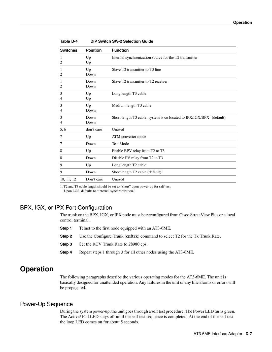
BPX, IGX, or IPX Port Configuration
Power-Up Sequence
Operation
Remote Loop Operation
Normal Operation
Terminal Operation
Operation
Commands
Table D-6 DIP Switch Settings
Table D-7 Command Summary Parameters Meaning
Specifications Table D-8 Status Display
Specifications
T3 interface
BPV NNN
Specifications
Power
T2 Interface
Mechanical
12Cisco BPX 8600 Series Reference
Glossary
ARI Alarm Relay Interface Card
ARC Alarm Relay Card
ARM Alarm Relay Module
ASM Alarm/Status Monitor Cards
Bandwidth reservation
B8ZS Bipolar with Eight Zero Suppression
Channel
BC-E1 Backcard E1
CAS Channel Associated Signalling
BPX Switch
Ccdv Compliant Cell Delay Variation
CCS Common Channel Signalling
Cell
CGA Carrier Group Alarm
Cell relay
Circuit line
Crosspoint switch
COS Class of Service
CSU Channel Service Unit
Dacs Digital Access and Control System
Dial Access Switching
DDS Digital Data Service
DS0 Digital Signal
DS1 Digital Signal
DTE Data Terminal Equipment
DSI Digital Speech Interpolation
ECN Explicit Congestion Notification
Fast EIA
Frame forwarding
Frame Relay Service
FPC FastPAD Back Card
Frame relay connection class
FTC FastPAD Trunk Card
IGX Switch
FTM FastPAD Trunk Module
Gateway
Isdn Integrated Services Digital Network
IPX Switch
Junction node
Junction trunk
Major alarm
Local alarm
Minor alarm
Local addressing
NPC Network Processor Card
Packet switching
NPM Network Processor Module
Nrm
PBX private branch exchange
Partially-interleaved EIA
PCM Pulse Code Modulation
PCR Peak Cell Rate
Remote alarm
Red alarm
Robbed bit signaling
921/Q.931
RS-449
SAR Segmentation and Reassembly
SCC System Clock Card
SCM System Clock Module
Speech detection
SVC switched virtual circuit
Split clock
Status Enquiry
Trm
Timestamp
Trunk
Trunk conditioning
VAD Voice Activity Detection
Voice Network Switching
VBR Variable Bit Rate
Virtual circuit
Yellow alarm
Cables
Cable redundancy
Adtf
ABR STD
ASI
ATM
ESP
Dlci
Fbtc
FRF.4 Frtt
SAM
Pnni
Snmp
Spvc
TSR
Tftp
VCI
VPI
Strongly agree Strongly disagree
Documentation Response Card
Business Reply Mail