Appendix L
Appendix L: Multiple VLANs with Computers
Overview
The
This example uses the Linksys
RVL200-to-SRW2048 Configuration
By default, Ethernet ports
On the RVL200, configure VLANs 2, 3, and 4. Set Ethernet port 4 to Trunk mode, and assign VLANs 2, 3, and 4 to Ethernet port 4. On the SRW2048, configure VLANs 2, 3, and 4, and then assign ports to the VLANs.
Multiple VLANs with Computers
![]()
![]()
![]()
![]()
![]()
![]()
![]() RVL200
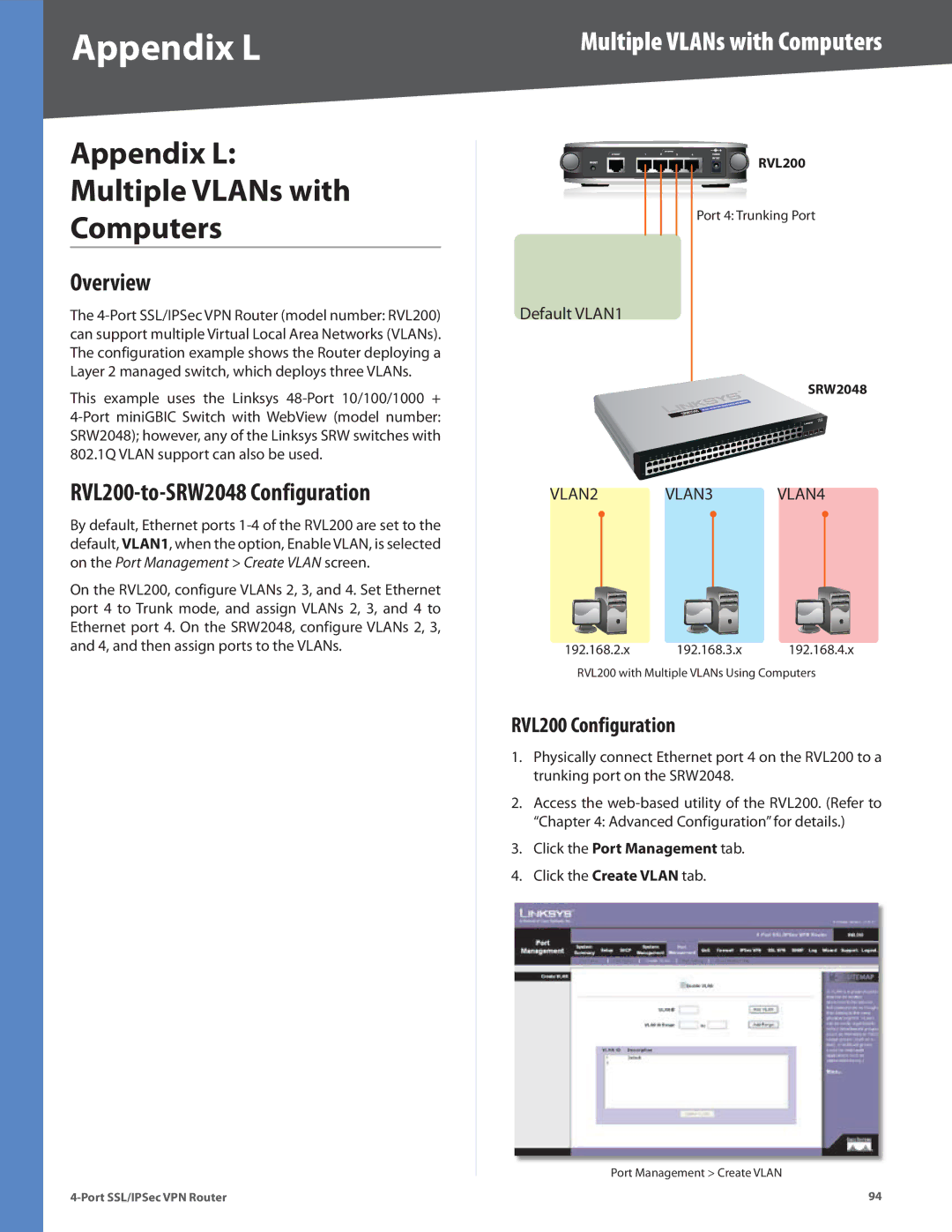
RVL200
Port 4: Trunking Port
Default VLAN1
SRW2048
VLAN2 VLAN3 VLAN4
192.168.2.x 192.168.3.x 192.168.4.x
RVL200 with Multiple VLANs Using Computers
RVL200 Configuration
1.Physically connect Ethernet port 4 on the RVL200 to a trunking port on the SRW2048.
2.Access the
3.Click the Port Management tab.
4.Click the Create VLAN tab.
Port Management > Create VLAN
94