Steps
1.Strip the insulation from the ends of the DC power wires, exposing approximately 13 mm (0.5 inch) of copper wire.
WARNING: Reversing polarity when connecting DC power wires can permanently damage the power supply or the system.
2.Insert the copper ends into the mating connectors and tighten the captive screws at the top of the mating connector using a #2 Phillips screwdriver.
WARNING: To protect the power supply from electrostatic discharge, the captive screws must be covered with the rubber cap before inserting the mating connector into the power supply.
3.Rotate the rubber cap clockwise to fix it over the captive screws.
4.Insert the mating connector into the power supply.
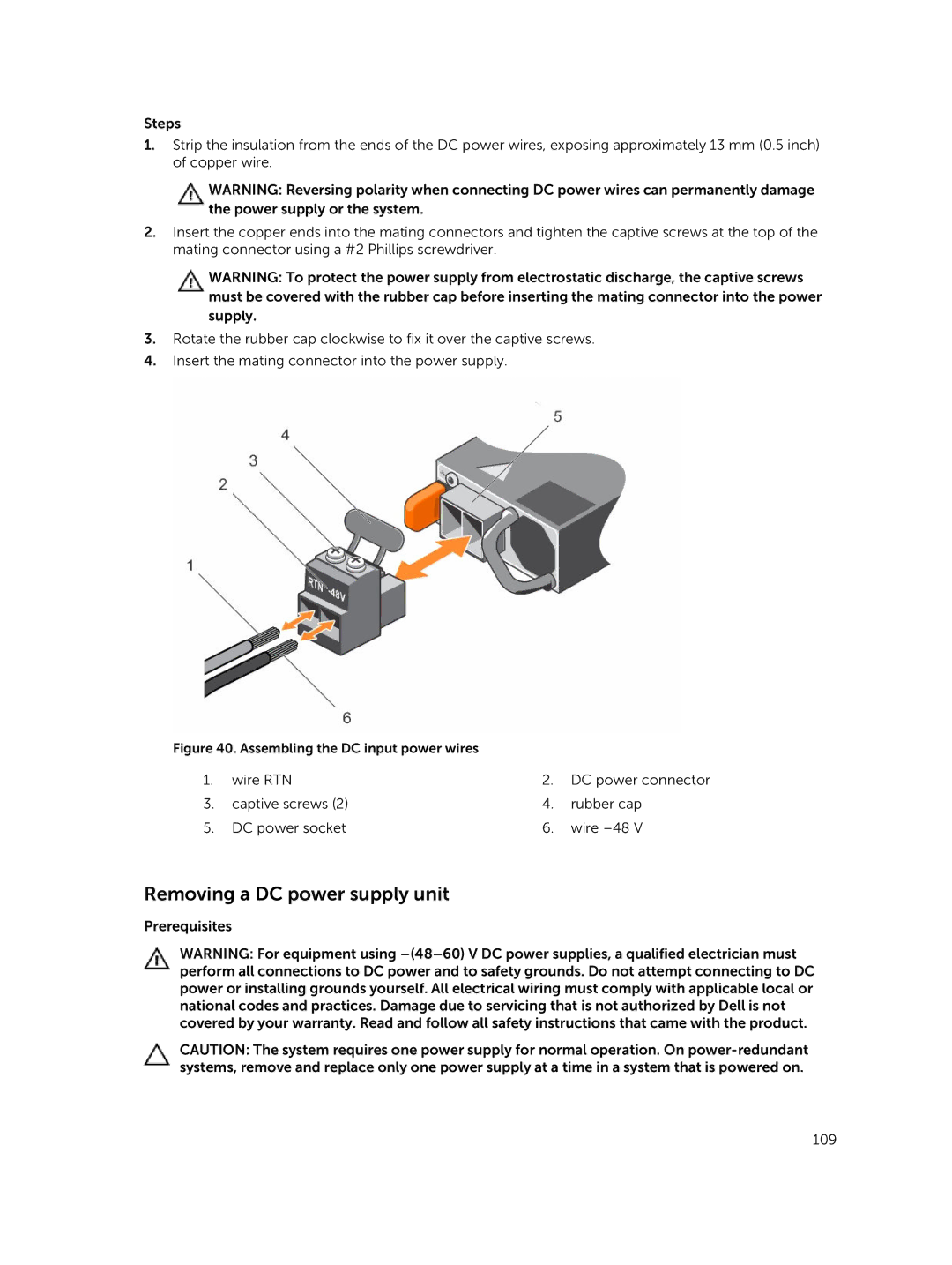
Figure 40. Assembling the DC input power wires |
|
| |
1. | wire RTN | 2. | DC power connector |
3. | captive screws (2) | 4. | rubber cap |
5. | DC power socket | 6. | wire |
Removing a DC power supply unit
Prerequisites
WARNING: For equipment using
CAUTION: The system requires one power supply for normal operation. On
109