Remote Display Options 24683B, C & D | Hydrastep 2468CB & 2468CD Manual |
4.7COMPONENT REPLACEMENT
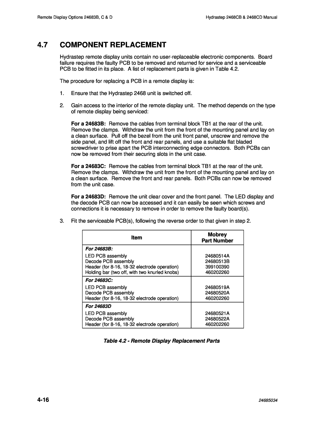
Hydrastep remote display units contain no
The procedure for replacing a PCB in a remote display is:
1.Ensure that the Hydrastep 2468 unit is switched off.
2.Gain access to the interior of the remote display unit. The method depends on the type of remote display being serviced:
For a 24683B: Remove the cables from terminal block TB1 at the rear of the unit. Remove the clamps. Withdraw the unit from the front of the mounting panel and lay on a clean surface. Pull off the bezel from the unit front panel, unscrew and remove the side panel, and lift off the front and rear panels, and use a suitable flat bladed screwdriver to prise apart the PCB interconnecting edge connectors. Both PCBs can now be removed from their securing slots in the unit case.
For a 24683C: Remove the cables from terminal block TB1 at the rear of the unit. Remove the clamps. Withdraw the unit from the front of the mounting panel and lay on a clean surface. Remove the front and rear panels. Both PCBs can now be removed from the unit case.
For a 24683D: Remove the unit clear cover and the front panel. The LED display and the decode PCB can now be accessed and it can easily be seen which screws and connections it is necessary to remove in order to remove the faulty board(s).
3.Fit the serviceable PCB(s), following the reverse order to that given in step 2.
Item
For 24683B:
LED PCB assembly Decode PCB assembly
Header (for
For 24683C:
LED PCB assembly Decode PCB assembly
Header (for
For 24683D
LED PCB assembly Decode PCB assembly
Header (for
Mobrey
Part Number
24680514A
24680513B
399100390
460202260
24680519A
24680520A
460202260
24680521A
24680522A
460202260
Table 4.2 - Remote Display Replacement Parts
| 24685034 |
