Relay Output Board Option | Hydrastep 2468CB and 2468CD Manual |
3a.3.1.3 Relay Energisation (‘In Steam’ or ‘In Water’) - SW5
This is a
3a.3.1.4 Electrode/Alarm Operation (RL1 Function Only) - SW6
Relay 1 can be configured to receive either an electrode input or it can be used as the ‘system fault’ relay (see Figure 3a.1 on page
3a.3.1.5 System Fault Output
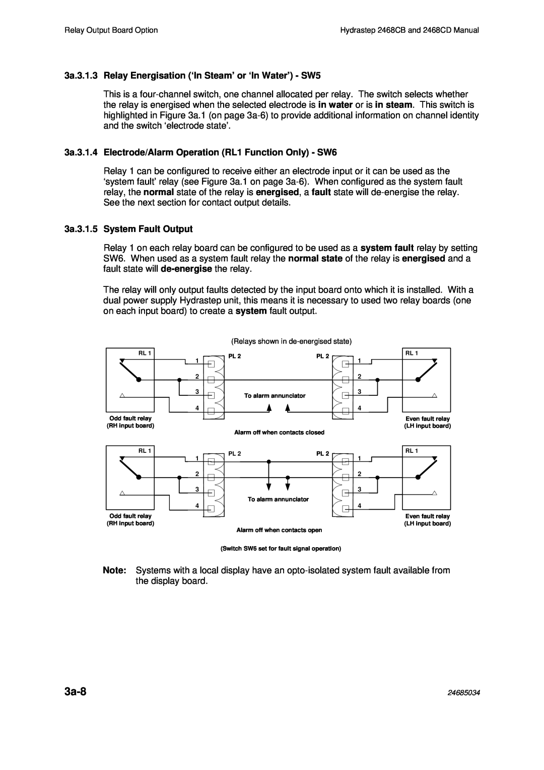
Relay 1 on each relay board can be configured to be used as a system fault relay by setting SW6. When used as a system fault relay the normal state of the relay is energised and a fault state will
The relay will only output faults detected by the input board onto which it is installed. With a dual power supply Hydrastep unit, this means it is necessary to used two relay boards (one on each input board) to create a system fault output.
|
| (Relays shown in |
| |
RL 1 |
| PL 2 | PL 2 | RL 1 |
| 1 | 1 | ||
|
|
| ||
| 2 |
|
| 2 |
| 3 |
| To alarm annunciator | 3 |
|
|
|
| |
| 4 |
|
| 4 |
Odd fault relay |
|
|
| Even fault relay |
(RH input board) |
| Alarm off when contacts closed | (LH input board) | |
|
|
| ||
RL 1 |
| PL 2 | PL 2 | RL 1 |
| 1 | 1 | ||
|
|
| ||
| 2 |
|
| 2 |
| 3 |
|
| 3 |
| 4 |
| To alarm annunciator | 4 |
|
|
| ||
Odd fault relay |
|
|
| Even fault relay |
(RH input board) |
|
|
| (LH input board) |
Alarm off when contacts open (Switch SW6 set for fault signal operation)
Note: Systems with a local display have an
| 24685034 |
