2468CB & 2468CD Dual Power Supply Version | Hydrastep 2468CB and 2468CD Manual |
2.5.1.2Pulsed Output Setting
As configured at the factory, the analogue output pulses if a fault condition occurs.
1.To disable this feature the split pad SP10 must be broken by cutting the track that passes between the pads.
2.To
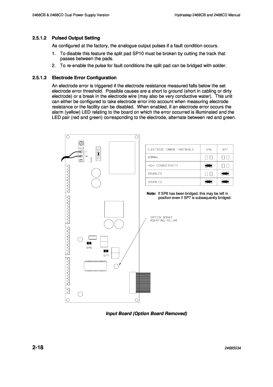
2.5.1.3Electrode Error Configuration
An electrode error is triggered if the electrode resistance measured falls below the set electrode error threshold. Possible causes are a short to ground (short in cabling or dirty electrode) or a break in the electrode wire (may also be very conductive water). This unit can either be configured to take electrode error into account when measuring electrode resistance or the facility can be disabled. When enabled, if an electrode error occurs the alarm (yellow) LED relating to the board on which the error occurred is illuminated and the LED pair (red and green) corresponding to the electrode, alternate between red and green.
Note: If SP6 has been bridged, this may be left in position even if SP7 is subsequently bridged.
Input Board (Option Board Removed)
| 24685034 |