Delay Relay Output Board Option | Hydrastep 2468CB and 2468CD Manual |
3B.3 DELAY RELAY BOARD CONFIGURATION
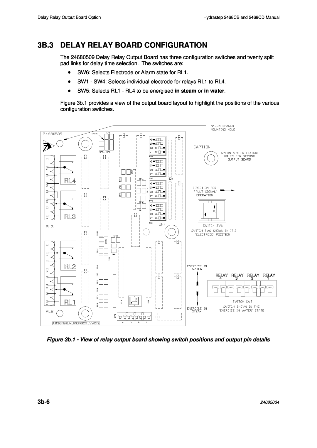
The 24680509 Delay Relay Output Board has three configuration switches and twenty split pad links for delay time selection. The switches are:
∙SW6: Selects Electrode or Alarm state for RL1.
∙SW1 - SW4: Selects individual electrode for relays RL1 to RL4.
∙SW5: Selects RL1 - RL4 to be energised in steam or in water.
Figure 3b.1 provides a view of the output board layout to highlight the positions of the various configuration switches.
Figure 3b.1 - View of relay output board showing switch positions and output pin details
| 24685034 |
