2468CB & 2468CD Dual Power Supply Version | Hydrastep 2468CB and 2468CD Manual |
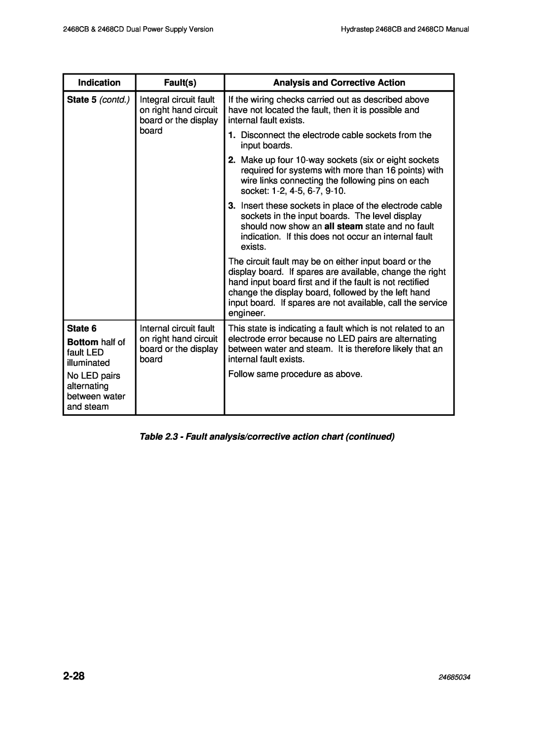
Indication | Fault(s) | Analysis and Corrective Action | |
|
|
| |
State 5 (contd.) | Integral circuit fault | If the wiring checks carried out as described above | |
| on right hand circuit | have not located the fault, then it is possible and | |
| board or the display | internal fault exists. | |
| board | 1. Disconnect the electrode cable sockets from the | |
|
| ||
|
| input boards. | |
|
| 2. Make up four | |
|
| required for systems with more than 16 points) with | |
|
| wire links connecting the following pins on each | |
|
| socket: | |
|
| 3. Insert these sockets in place of the electrode cable | |
|
| sockets in the input boards. The level display | |
|
| should now show an all steam state and no fault | |
|
| indication. If this does not occur an internal fault | |
|
| exists. | |
|
| The circuit fault may be on either input board or the | |
|
| display board. If spares are available, change the right | |
|
| hand input board first and if the fault is not rectified | |
|
| change the display board, followed by the left hand | |
|
| input board. If spares are not available, call the service | |
|
| engineer. | |
State 6 | Internal circuit fault | This state is indicating a fault which is not related to an | |
Bottom half of | on right hand circuit | electrode error because no LED pairs are alternating | |
board or the display | between water and steam. It is therefore likely that an | ||
fault LED | |||
board | internal fault exists. | ||
illuminated | |||
| Follow same procedure as above. | ||
No LED pairs |
| ||
alternating |
|
| |
between water |
|
| |
and steam |
|
| |
|
|
| |
| Table 2.3 - Fault analysis/corrective action chart (continued) | ||
| 24685034 |