2468CB & 2468CD Dual Power Supply Version | Hydrastep 2468CB and 2468CD Manual |
2.4.2ELECTRICAL INSTALLATION
This section deals with the interconnection between the electrodes and the electronic enclosure, the connection of the ac mains power supply to the electronic enclosure and the analogue output connections from the electronic enclosure.
2.4.2.1Electrode Connections Hydrastep Electrode Cables
Special electrode cable assemblies of length 3, 10, 18 or 30 metres are provided with the system for connecting the Hydrastep 2468 Electronic Enclosure to the Water Column Electrodes. The cable looms are
The conductors are colour coded for ease of installation and have pure nickel ring clamps fitted at one end for connection to the electrodes. A set of wire crimps is provided for use on the Enclosure connections.
The black conductors in each cable are used for the EARTH terminations, leaving eight pairs of coloured conductors for connection to the electrodes. At least one cable assembly is required and certain conductor pairs in the cables will be redundant. The exceptions are the 8, 16 and 32 electrode systems where all the conductors in the cables are fully used.
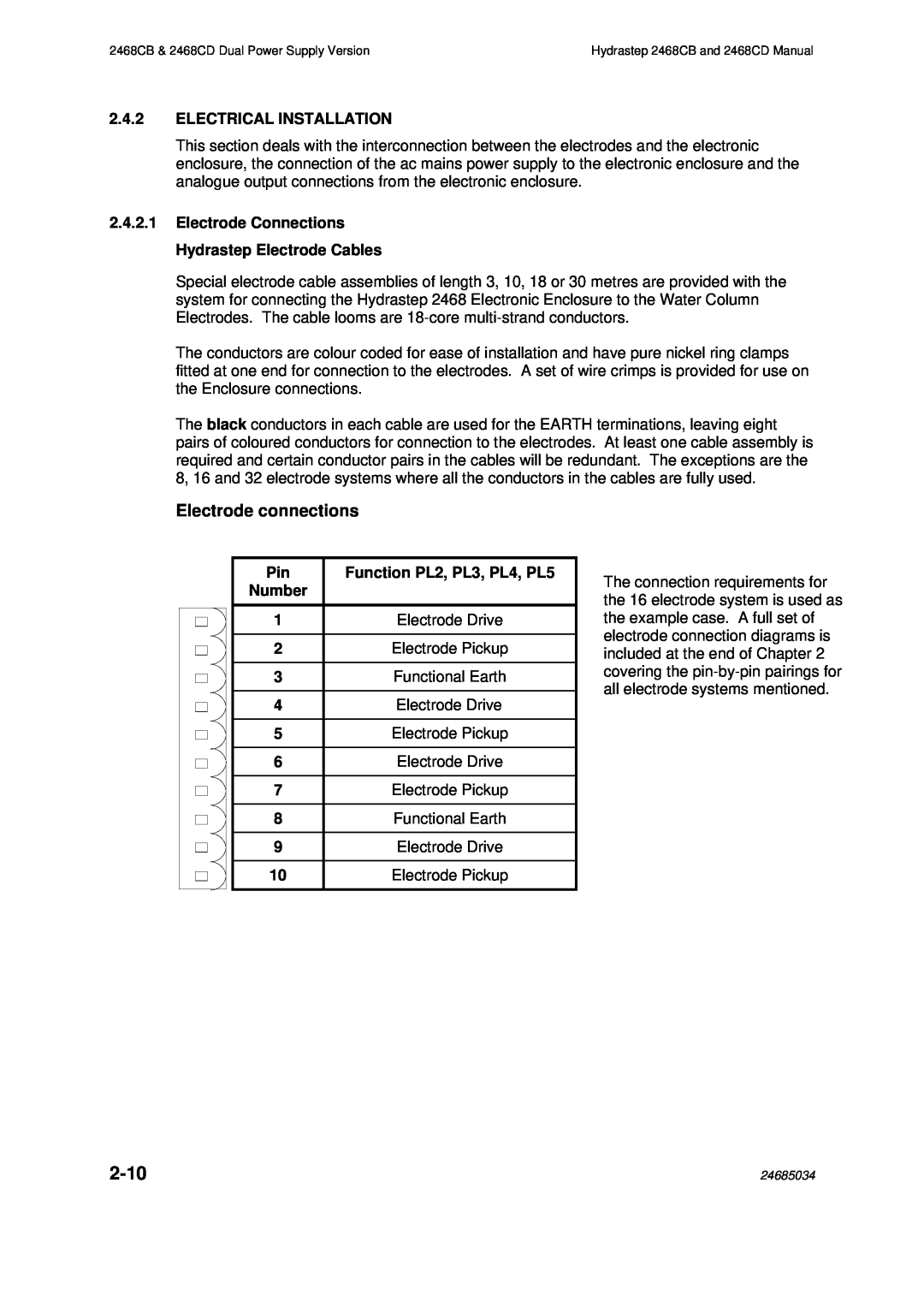
Electrode connections
Pin | Function PL2, PL3, PL4, PL5 |
Number |
|
|
|
1 | Electrode Drive |
|
|
2 | Electrode Pickup |
|
|
3 | Functional Earth |
|
|
4 | Electrode Drive |
|
|
5 | Electrode Pickup |
|
|
6 | Electrode Drive |
|
|
7 | Electrode Pickup |
|
|
8 | Functional Earth |
|
|
9 | Electrode Drive |
|
|
10 | Electrode Pickup |
The connection requirements for the 16 electrode system is used as the example case. A full set of electrode connection diagrams is included at the end of Chapter 2 covering the
| 24685034 |
