Hydrastep 2468CB & 2468CD Manual | Remote Display Options 24683B, C & D |
4.4.4CONNECTING CABLES TO THE REMOTE DISPLAY
The following procedure can be used for each remote display that is to be connected:
1.Gain access to the remote display terminal block. On the 24683B and 24683C remote displays the terminal block is located at the rear of the unit. The terminal block of the 24683D remote display is located within the unit and must be accessed as described in Section 4.3.2.
2.Prepare the cable ends and fit identity sleeves to the leads.
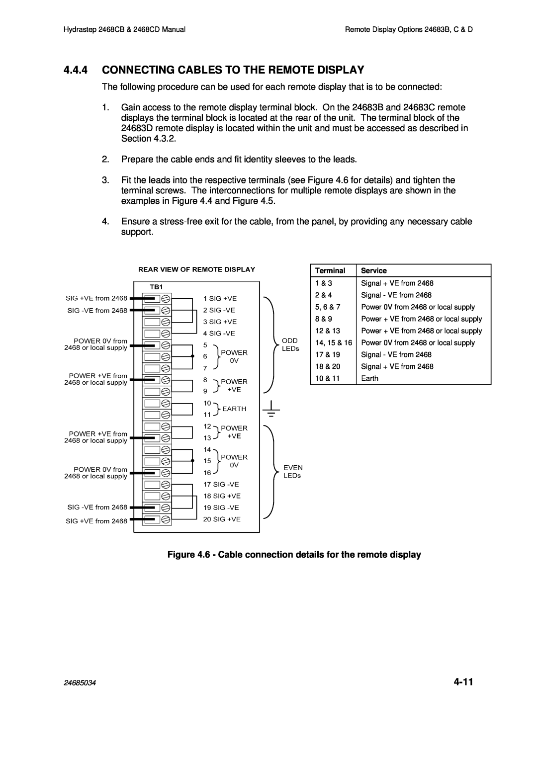
3.Fit the leads into the respective terminals (see Figure 4.6 for details) and tighten the terminal screws. The interconnections for multiple remote displays are shown in the examples in Figure 4.4 and Figure 4.5.
4.Ensure a
Terminal | Service |
1 & 3 | Signal + VE from 2468 |
2 & 4 | Signal - VE from 2468 |
5, 6 & 7 | Power 0V from 2468 or local supply |
8 & 9 | Power + VE from 2468 or local supply |
12 & 13 | Power + VE from 2468 or local supply |
14, 15 & 16 | Power 0V from 2468 or local supply |
17 & 19 | Signal - VE from 2468 |
18 & 20 | Signal + VE from 2468 |
10 & 11 | Earth |
|
|
Figure 4.6 - Cable connection details for the remote display
24685034 |
|