Remote Display Options 24683B, C & D | Hydrastep 2468CB & 2468CD Manual |
4.2CONFIGURATION
All remote displays can be configured for operation with 8 to 16 electrodes (two LEDs per electrode) or 18 to 32 electrodes (one LED per electrode). Remote displays are supplied ready for operation with 8 to 16 electrodes. If a remote display is required to operate with 18 to 32 electrodes then it must be reconfigured. The procedure for each type of remote display is described below.
4.2.1RECONFIGURING THE 24683B AND 24683C REMOTE DISPLAY
The procedure for reconfiguring the 24683B and 24683C for operation with 18 to 32 electrodes is:
1.Undo the four screws securing the rear panel and remove the panel.
2.Withdraw the decoding PCB from the rear of the display unit. (Some force may be necessary, initially, to disengage the decoding PCB from the LED PCB.)
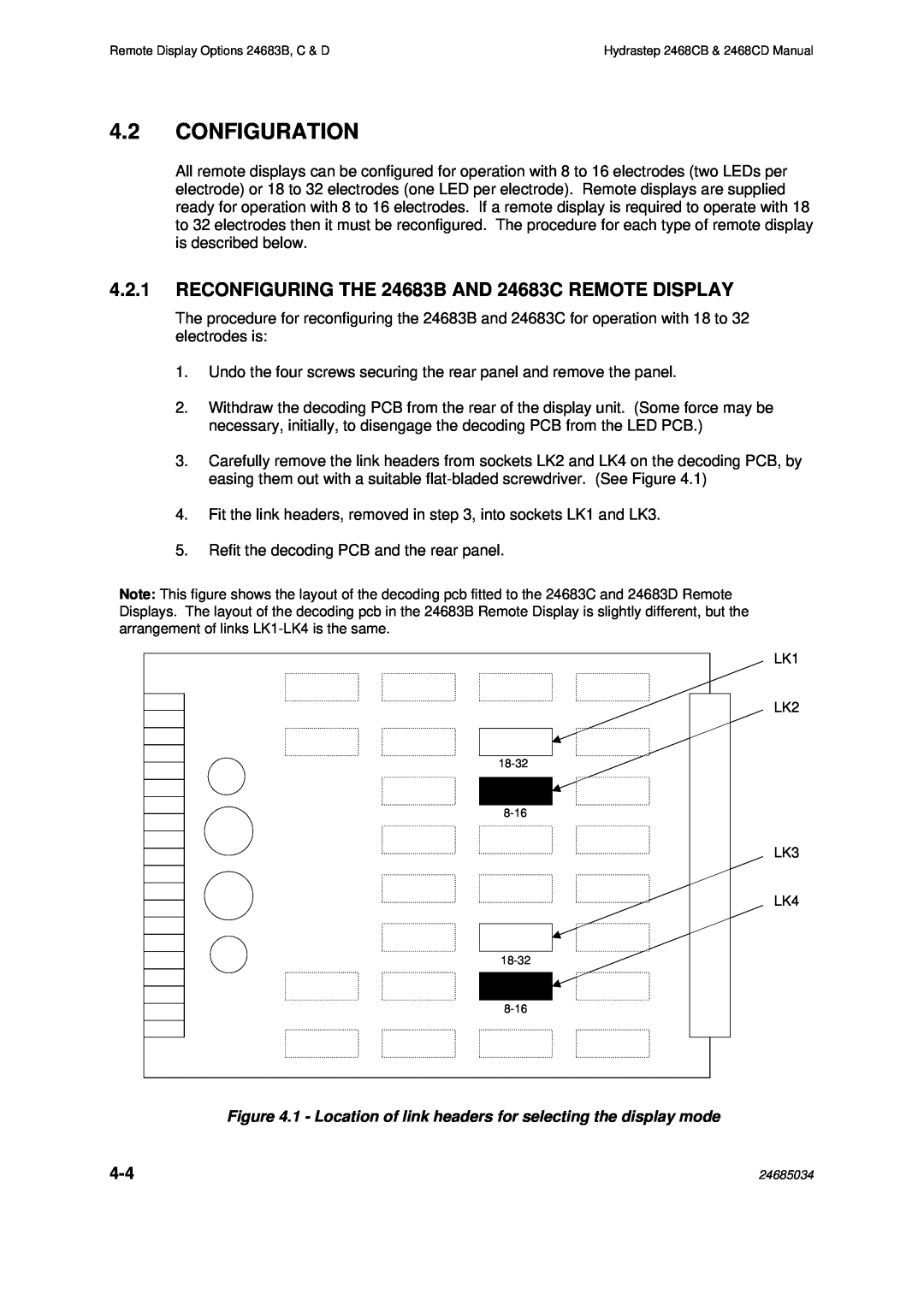
3.Carefully remove the link headers from sockets LK2 and LK4 on the decoding PCB, by easing them out with a suitable
4.Fit the link headers, removed in step 3, into sockets LK1 and LK3.
5.Refit the decoding PCB and the rear panel.
Note: This figure shows the layout of the decoding pcb fitted to the 24683C and 24683D Remote Displays. The layout of the decoding pcb in the 24683B Remote Display is slightly different, but the arrangement of links
LK1
LK2
LK3
LK4
Figure 4.1 - Location of link headers for selecting the display mode
24685034 |