Hydrastep 2468CB and 2468CD Manual | 2468CB & 2468CD Dual Power Supply Version |
2.4.2.5Analogue Output Connection
WARNING Mains voltages are present in this instrument when power is connected.
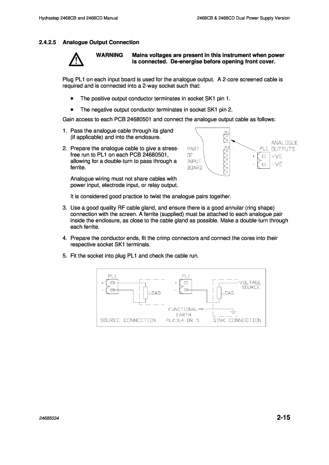
Plug PL1 on each input board is used for the analogue output. A
∙The positive output conductor terminates in socket SK1 pin 1.
∙The negative output conductor terminates in socket SK1 pin 2.
Gain access to each PCB 24680501 and connect the analogue output cable as follows:
1. Pass the analogue cable through its gland (if applicable) and into the enclosure.
2. Prepare the analogue cable to give a stress- free run to PL1 on each PCB 24680501, allowing for a
Analogue wiring must not share cables with power input, electrode input, or relay output.
It is considered good practice to twist the analogue pairs together.
3.Use a good quality RF cable gland, and ensure there is a good annular (ring shape) connection with the screen. A ferrite (supplied) must be attached to each analogue pair inside the enclosure, as close to the cable gland as possible. Make a
4.Prepare the conductor ends, fit the crimp connectors and connect the cores into their respective socket SK1 terminals.
5.Fit the socket into plug PL1 and check the cable run.
24685034 |
|