Hydrastep 2468CB & 2468CD Manual |
3C.2.3 ELECTRICAL INSTALLATION 3c.2.3.1 PCB Interconnections
Signal interconnection between the input board (PCB 1) and the output board (PCB 5) is direct via the SK1/PL1
This
3c.2.3.2 Opto-Isolated Output Connections
The
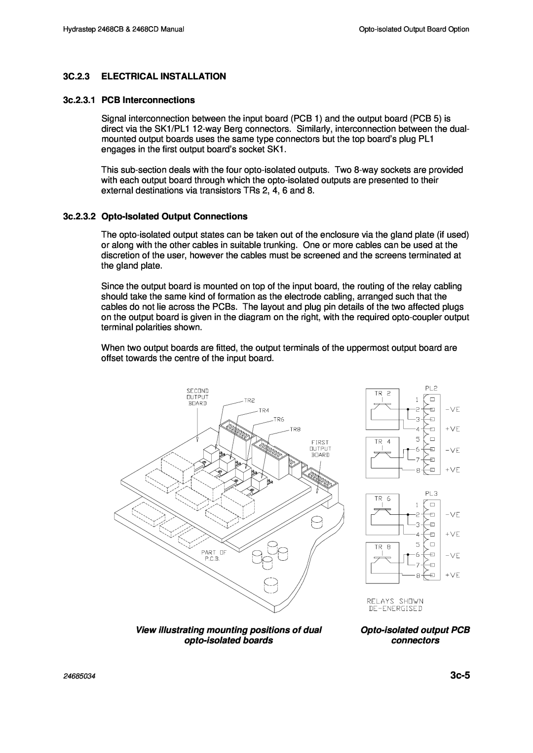
Since the output board is mounted on top of the input board, the routing of the relay cabling should take the same kind of formation as the electrode cabling, arranged such that the cables do not lie across the PCBs. The layout and plug pin details of the two affected plugs on the output board is given in the diagram on the right, with the required
When two output boards are fitted, the output terminals of the uppermost output board are offset towards the centre of the input board.
View illustrating mounting positions of dual | |
connectors |
24685034 |
|