2468CB & 2468CD Dual Power Supply Version | Hydrastep 2468CB and 2468CD Manual |
2.5.2.3‘Switching Threshold’ Setting
WARNING Mains voltages are present in this instrument when power is connected.
1.Disconnect the power supply. Gain access to PCB 24680515 by opening the cover.
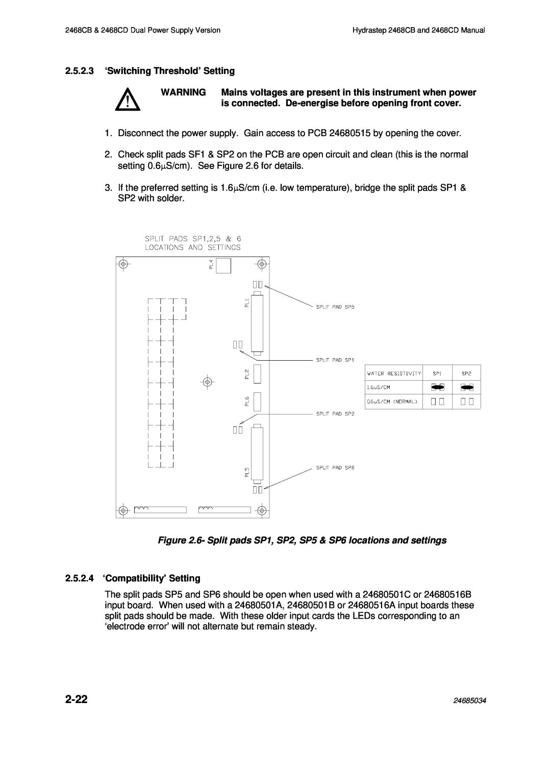
2.Check split pads SF1 & SP2 on the PCB are open circuit and clean (this is the normal setting 0.6μS/cm). See Figure 2.6 for details.
3.If the preferred setting is 1.6μS/cm (i.e. low temperature), bridge the split pads SP1 & SP2 with solder.
Figure 2.6- Split pads SP1, SP2, SP5 & SP6 locations and settings
2.5.2.4 ‘Compatibility’ Setting
The split pads SP5 and SP6 should be open when used with a 24680501C or 24680516B input board. When used with a 24680501A, 24680501B or 24680516A input boards these split pads should be made. With these older input cards the LEDs corresponding to an ‘electrode error’ will not alternate but remain steady.
| 24685034 |
