Hydrastep 2468CB and 2468CD Manual | 2468CB & 2468CD Dual Power Supply Version |
2.1INTRODUCTION
This chapter introduces the dual power supply version of the Hydrastep 2468 Electronic Gauging System, its mechanical installation, system configuration, simple fault analysis/corrective action capability and its specification.
2.2ELECTRODE CABLING SYSTEM
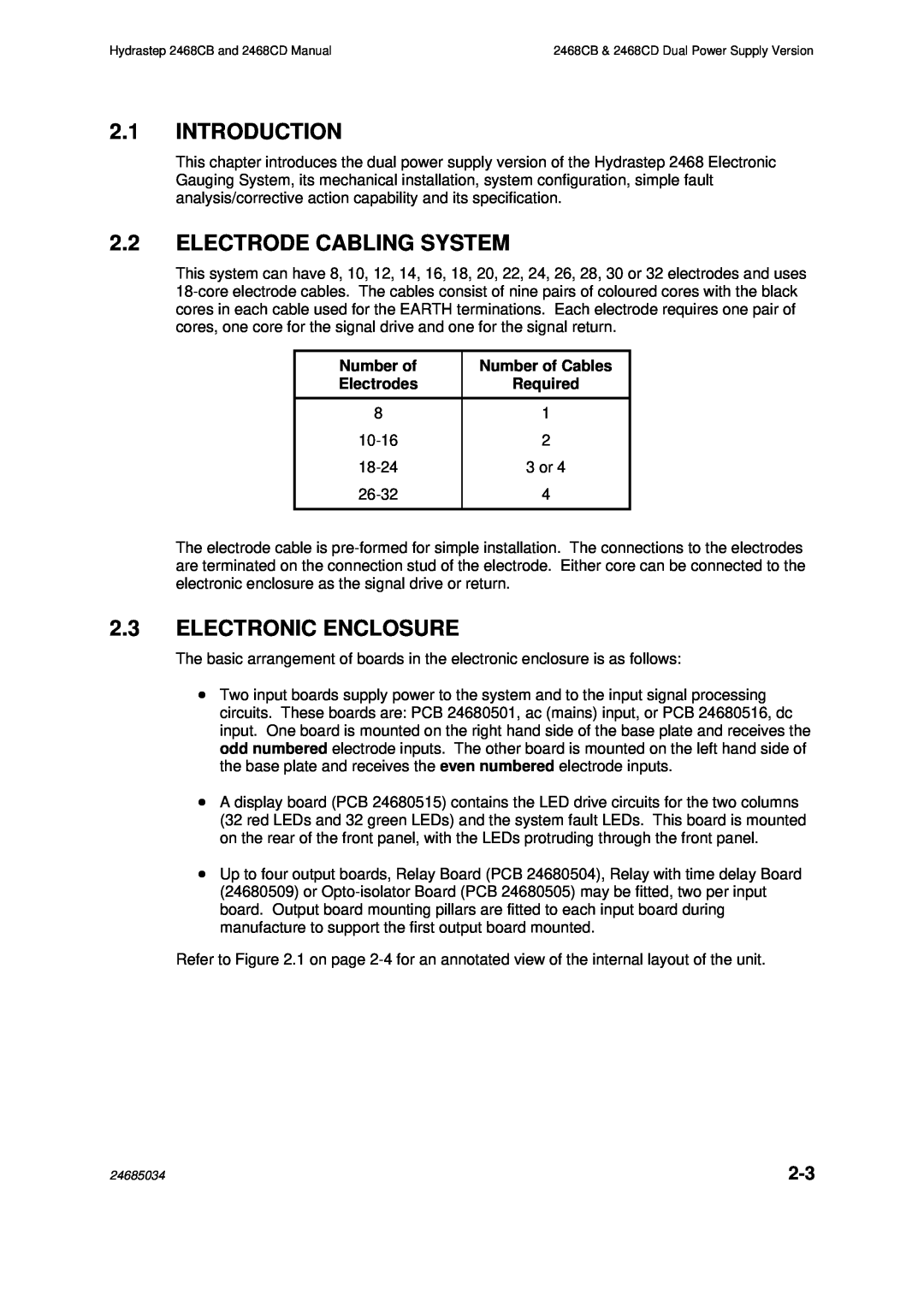
This system can have 8, 10, 12, 14, 16, 18, 20, 22, 24, 26, 28, 30 or 32 electrodes and uses
Number of | Number of Cables |
Electrodes | Required |
|
|
8 | 1 |
2 | |
3 or 4 | |
4 | |
|
|
The electrode cable is
2.3ELECTRONIC ENCLOSURE
The basic arrangement of boards in the electronic enclosure is as follows:
∙Two input boards supply power to the system and to the input signal processing circuits. These boards are: PCB 24680501, ac (mains) input, or PCB 24680516, dc input. One board is mounted on the right hand side of the base plate and receives the odd numbered electrode inputs. The other board is mounted on the left hand side of the base plate and receives the even numbered electrode inputs.
∙A display board (PCB 24680515) contains the LED drive circuits for the two columns (32 red LEDs and 32 green LEDs) and the system fault LEDs. This board is mounted on the rear of the front panel, with the LEDs protruding through the front panel.
∙Up to four output boards, Relay Board (PCB 24680504), Relay with time delay Board (24680509) or
Refer to Figure 2.1 on page
24685034 |