Delay Relay Output Board Option | Hydrastep 2468CB and 2468CD Manual |
3B.2.2 MECHANICAL INSTALLATION
The output board is mounted directly on top of the input board. The input board is supplied with three nylon spacers fitted. The output board is then aligned on its Berg socket/plug interconnection (PL1/SK1) and input
When two output boards are required to be mounted on an input board, the second output board is mounted on three nylon spacers fitted on the first mounted output board.
3b.2.2.1 Fitting the Nylon Spacers to the Delay Relay Output Board
The spacers fit into the holes within the
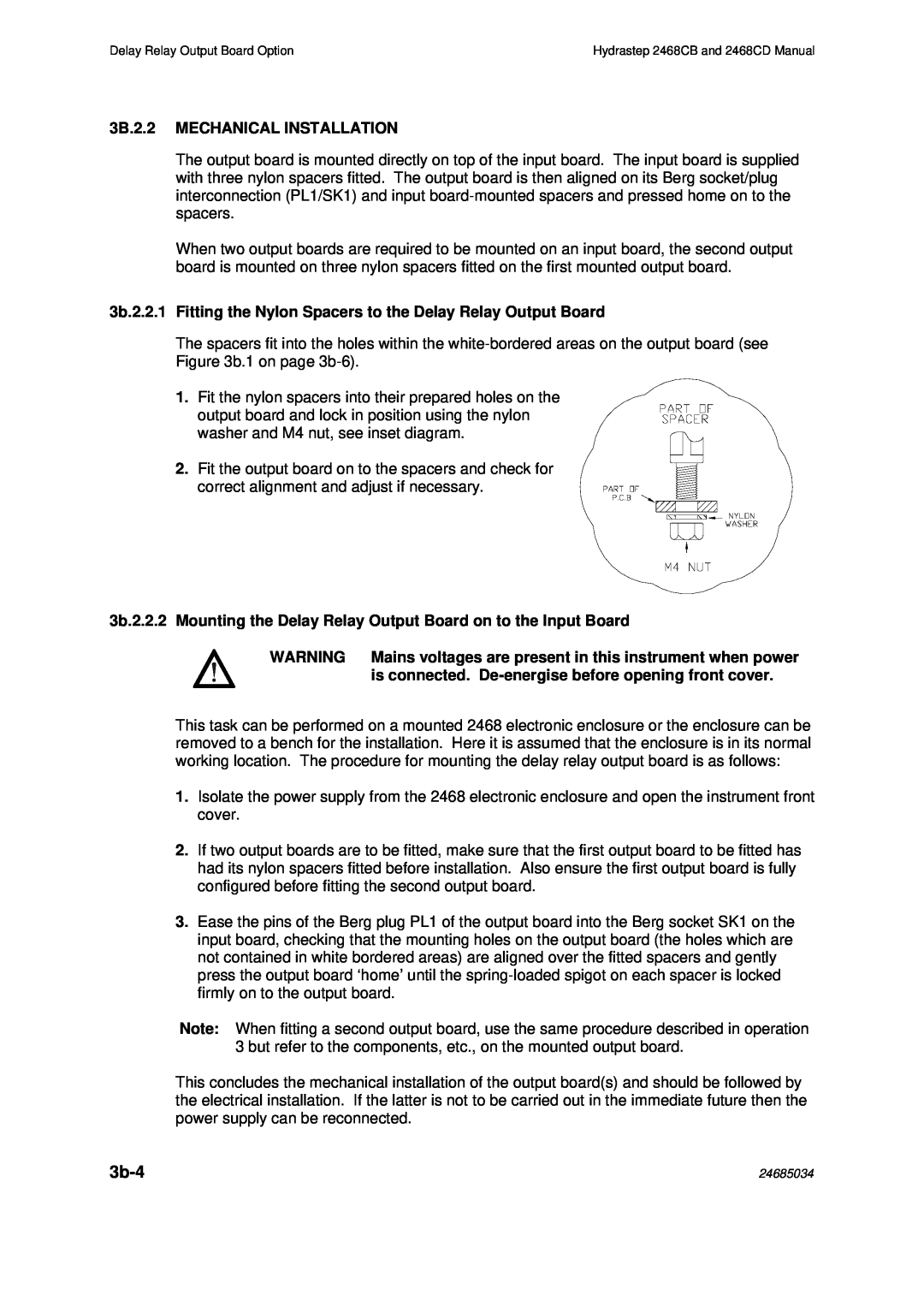
1. Fit the nylon spacers into their prepared holes on the output board and lock in position using the nylon washer and M4 nut, see inset diagram.
2. Fit the output board on to the spacers and check for correct alignment and adjust if necessary.
3b.2.2.2 Mounting the Delay Relay Output Board on to the Input Board
WARNING Mains voltages are present in this instrument when power is connected.
This task can be performed on a mounted 2468 electronic enclosure or the enclosure can be removed to a bench for the installation. Here it is assumed that the enclosure is in its normal working location. The procedure for mounting the delay relay output board is as follows:
1.Isolate the power supply from the 2468 electronic enclosure and open the instrument front cover.
2.If two output boards are to be fitted, make sure that the first output board to be fitted has had its nylon spacers fitted before installation. Also ensure the first output board is fully configured before fitting the second output board.
3.Ease the pins of the Berg plug PL1 of the output board into the Berg socket SK1 on the input board, checking that the mounting holes on the output board (the holes which are not contained in white bordered areas) are aligned over the fitted spacers and gently press the output board ‘home’ until the
Note: When fitting a second output board, use the same procedure described in operation 3 but refer to the components, etc., on the mounted output board.
This concludes the mechanical installation of the output board(s) and should be followed by the electrical installation. If the latter is not to be carried out in the immediate future then the power supply can be reconnected.
| 24685034 |