2468CB & 2468CD Dual Power Supply Version | Hydrastep 2468CB and 2468CD Manual |
2.5.2DISPLAY BOARD 24680515
The Display Board needs to know how many electrodes are being used and if one or two input boards are being used. A centrally mounted
Sockets are also provided at LK2, LK3, LK4 and LK5 locations (see Figure 2.5), to select an 8 - 16 (two LEDs per electrode) display mode or an 18 - 32 (one LED per electrode) display mode. For hazardous area applications, links 2, 3, 4 and 5, when fitted, must be secured into the sockets using a cable tie passed underneath the socket base.
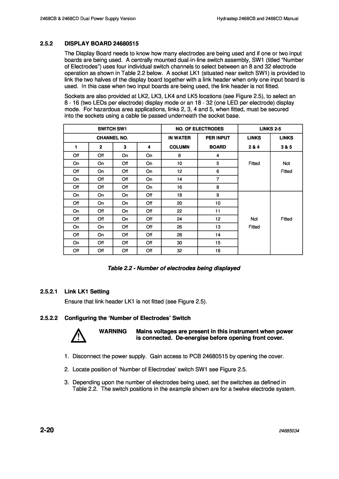
| SWITCH SW1 |
| NO. OF ELECTRODES | LINKS | |||
|
|
|
|
|
|
|
|
| CHANNEL NO. |
| IN WATER | PER INPUT | LINKS | LINKS | |
|
|
|
|
|
|
|
|
1 | 2 | 3 | 4 | COLUMN | BOARD | 2 & 4 | 3 & 5 |
|
|
|
|
|
|
|
|
Off | Off | On | On | 8 | 4 |
|
|
|
|
|
|
|
|
|
|
On | On | Off | On | 10 | 5 | Fitted | Not |
|
|
|
|
|
|
|
|
Off | On | Off | On | 12 | 6 |
| Fitted |
|
|
|
|
|
|
|
|
On | Off | Off | On | 14 | 7 |
|
|
Off | Off | Off | On | 16 | 8 |
|
|
|
|
|
|
|
|
|
|
On | On | On | Off | 18 | 9 |
|
|
Off | On | On | Off | 20 | 10 |
|
|
|
|
|
|
|
|
|
|
On | Off | On | Off | 22 | 11 |
|
|
|
|
|
|
|
|
|
|
Off | Off | On | Off | 24 | 12 | Not | Fitted |
On | On | Off | Off | 26 | 13 | Fitted |
|
|
|
|
|
|
|
|
|
Off | On | Off | Off | 28 | 14 |
|
|
|
|
|
|
|
|
|
|
On | Off | Off | Off | 30 | 15 |
|
|
|
|
|
|
|
|
|
|
Off | Off | Off | Off | 32 | 16 |
|
|
|
|
|
|
|
|
|
|
Table 2.2 - Number of electrodes being displayed
2.5.2.1Link LK1 Setting
Ensure that link header LK1 is not fitted (see Figure 2.5).
2.5.2.2Configuring the ‘Number of Electrodes’ Switch
WARNING Mains voltages are present in this instrument when power is connected.
1.Disconnect the power supply. Gain access to PCB 24680515 by opening the cover.
2.Locate position of ‘Number of Electrodes’ switch SW1 see Figure 2.5.
3.Depending upon the number of electrodes being used, set the switches as defined in Table 2.2. The switch positions in the example shown are for a twelve electrode system.
| 24685034 |