Hydrastep 2468CB & 2468CD Manual |
3c.3.1.2 Electrode/Alarm Operation (output 1 function only) - SW6
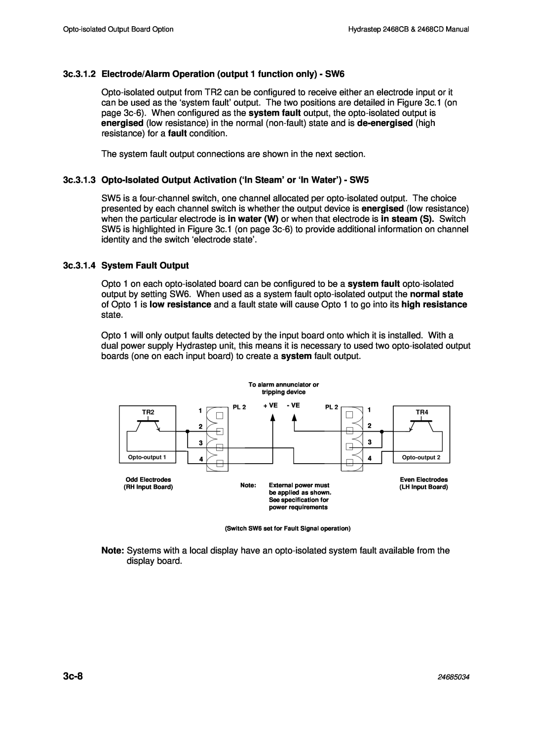
The system fault output connections are shown in the next section.
3c.3.1.3
SW5 is a
3c.3.1.4 System Fault Output
Opto 1 on each
Opto 1 will only output faults detected by the input board onto which it is installed. With a dual power supply Hydrastep unit, this means it is necessary to used two
|
|
| To alarm annunciator or |
|
|
|
| tripping device |
|
TR2 | 1 | PL 2 | + VE - VE | PL 2 |
|
|
| ||
| 2 |
|
|
|
| 3 |
|
|
|
4 |
|
|
|
Odd Electrodes | Note: | External power must |
(RH Input Board) | ||
|
| be applied as shown. |
|
| See specification for |
|
| power requirements |
1
2
3
4
TR4
Even Electrodes (LH Input Board)
(Switch SW6 set for Fault Signal operation)
Note: Systems with a local display have an
| 24685034 |