56 Chapter 7 “1+N” System
7.4.3 Power Cables
The wiring of power cables is similar to that of single module system. Refer to 3.1 Power Cabling.
The bypass and the main input sources must be referenced to the same neutral potential and input earth leakage monitoring devices, if installed, must be located upstream of the common neutral sinking point.
7.4.4 Control Cables
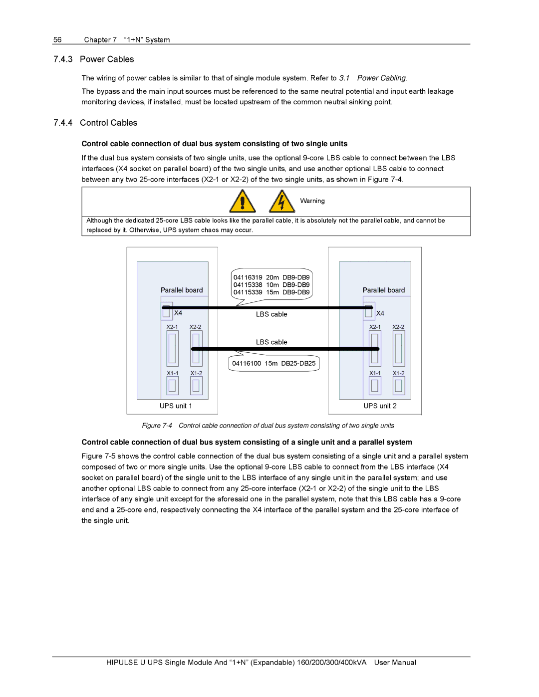
Control cable connection of dual bus system consisting of two single units
If the dual bus system consists of two single units, use the optional
Warning
Although the dedicated
|
| 04116319 | 20m |
|
|
|
Parallel board | 04115338 | 10m | Parallel board | |||
04115339 | 15m | |||||
X4 |
| LBS cable | X4 |
| ||
|
|
| ||||
|
| LBS cable |
|
| ||
|
| 04116100 15m |
|
| ||
|
|
| ||||
UPS unit 1 | UPS unit 2 |
Figure 7-4 Control cable connection of dual bus system consisting of two single units
Control cable connection of dual bus system consisting of a single unit and a parallel system
Figure 7-5 shows the control cable connection of the dual bus system consisting of a single unit and a parallel system composed of two or more single units. Use the optional 9-core LBS cable to connect from the LBS interface (X4 socket on parallel board) of the single unit to the LBS interface of any single unit in the parallel system; and use another optional LBS cable to connect from any 25-core interface (X2-1 or X2-2) of the single unit to the LBS interface of any single unit except for the aforesaid one in the parallel system, note that this LBS cable has a 9-core end and a 25-core end, respectively connecting the X4 interface of the parallel system and the 25-core interface of the single unit.
HIPULSE U UPS Single Module And “1+N” (Expandable) 160/200/300/400kVA User Manual
