68 | Appendix 1 Transportation Restraints Removing Procedures |
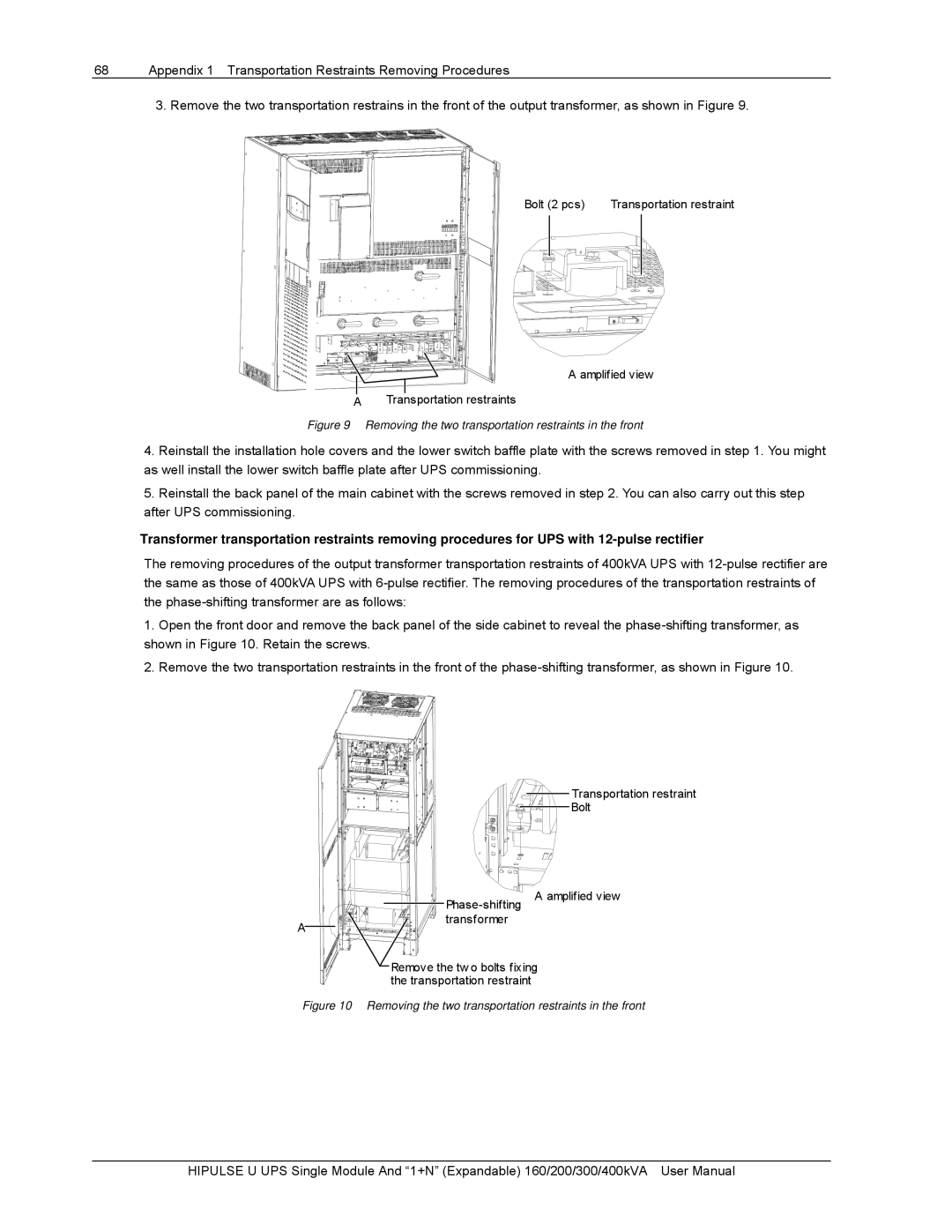
3. Remove the two transportation restrains in the front of the output transformer, as shown in Figure 9.
|
|
| Bolt (2 pcs) |
|
|
|
| Transportation restraint | |||||||||||||||||||||||||||||||||||||||||
|
|
|
|
|
|
|
|
|
|
|
|
|
|
|
|
|
|
|
|
|
|
|
|
|
|
|
|
|
|
|
|
|
|
|
|
|
|
|
|
|
|
|
|
|
|
|
|
|
|
|
|
|
|
|
|
|
|
|
|
|
|
|
|
|
|
|
|
|
|
|
|
|
|
|
|
|
|
|
|
|
|
|
|
|
|
|
|
|
|
|
|
|
|
|
|
|
|
|
|
|
|
|
|
|
|
|
|
|
|
|
|
|
|
|
|
|
|
|
|
|
|
|
|
|
|
|
|
|
|
|
|
|
|
|
|
|
|
|
|
|
|
|
|
|
|
|
|
|
|
|
|
|
|
|
|
|
|
|
|
|
|
|
|
|
|
|
|
|
|
|
|
|
|
|
|
|
|
|
|
|
|
|
|
|
|
|
|
|
|
|
|
|
|
|
|
|
|
|
|
|
|
|
|
|
|
|
|
|
|
|
|
|
|
|
|
|
|
|
|
|
|
|
|
|
|
|
|
|
|
|
|
|
|
|
|
|
|
|
|
|
|
|
|
|
|
|
|
|
|
|
|
|
|
|
|
|
|
|
|
|
|
|
|
|
|
|
|
|
|
|
|
|
|
|
|
|
|
|
|
|
|
|
|
|
|
|
|
|
|
|
|
|
|
|
|
|
|
|
|
|
|
|
|
|
|
|
|
|
|
|
|
|
|
|
|
|
|
|
|
|
|
|
|
|
|
|
|
|
|
|
|
|
|
|
|
|
|
|
|
|
|
|
|
|
|
|
|
|
|
A amplified view
A | Transportation restraints |
Figure 9 Removing the two transportation restraints in the front
4.Reinstall the installation hole covers and the lower switch baffle plate with the screws removed in step 1. You might as well install the lower switch baffle plate after UPS commissioning.
5.Reinstall the back panel of the main cabinet with the screws removed in step 2. You can also carry out this step after UPS commissioning.
Transformer transportation restraints removing procedures for UPS with
The removing procedures of the output transformer transportation restraints of 400kVA UPS with
1.Open the front door and remove the back panel of the side cabinet to reveal the
2.Remove the two transportation restraints in the front of the
A


 Transportation restraint
Bolt
| A amplified view |
transformer |
|
Remove the tw o bolts fixing the transportation restraint
Figure 10 Removing the two transportation restraints in the front
HIPULSE U UPS Single Module And “1+N” (Expandable) 160/200/300/400kVA User Manual