Chapter 3 Electrical Installation | 25 |
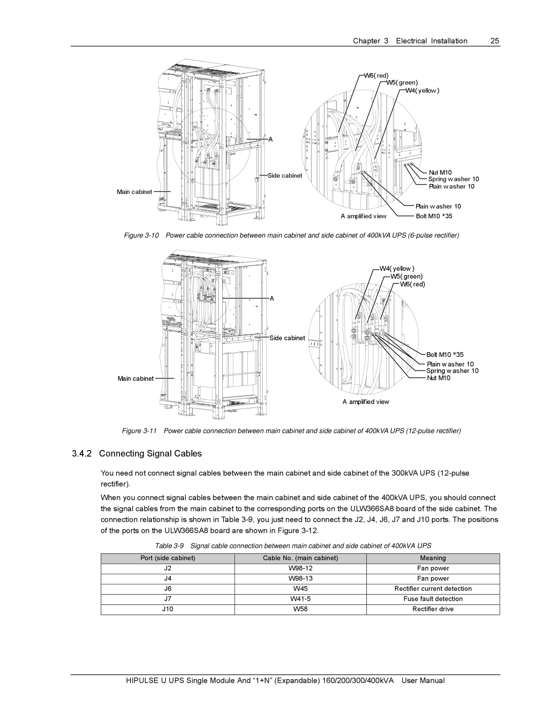
Main cabinet |
A |
Side cabinet |
W6( red)
W5( green)
W4( yellow )
Nut M10 |
Spring w asher 10 |
Plain w asher 10
Plain w asher 10
A amplified view |
| Bolt M10 *35 |
|
Figure 3-10 Power cable connection between main cabinet and side cabinet of 400kVA UPS (6-pulse rectifier)
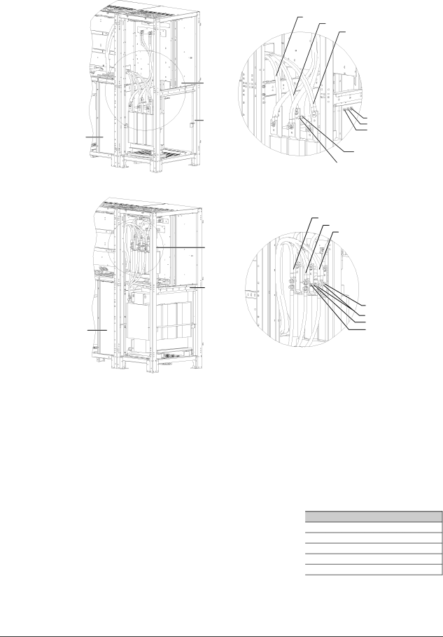
Main cabinet |
A |
Side cabinet |
W4( yellow )
W5( green)
W6( red)
Bolt M10 *35
Plain w asher 10
Spring w asher 10
Nut M10
A amplified view
Figure 3-11 Power cable connection between main cabinet and side cabinet of 400kVA UPS (12-pulse rectifier)
3.4.2 Connecting Signal Cables
You need not connect signal cables between the main cabinet and side cabinet of the 300kVA UPS
When you connect signal cables between the main cabinet and side cabinet of the 400kVA UPS, you should connect the signal cables from the main cabinet to the corresponding ports on the ULW366SA8 board of the side cabinet. The connection relationship is shown in Table
Table
Port (side cabinet) | Cable No. (main cabinet) |
J2 | |
J4 | |
J6 | W45 |
J7 |
|
J10 | W58 |
Meaning
Fan power Fan power
Rectifier current detection
Fuse fault detection
Rectifier drive
HIPULSE U UPS Single Module And “1+N” (Expandable) 160/200/300/400kVA User Manual