|
|
|
| Chapter 3 Electrical Installation | 21 |
| 1. Battery environment, battery ground fault and generator supply detection port (J4) |
| |||
| The battery environment, battery ground fault and generator supply detection port is described in Table |
| |||
| Table |
| |||
|
|
|
|
|
|
| Position | Name |
| Description |
|
| J4.1 | ENV3 |
| Battery environment detection (NC) |
|
| J4.2 | BtG |
| Battery ground fault detection (NC) |
|
| J4.3 | GEN1,2 |
| On generator (NO) |
|
| J4.4 | +12V |
| +12V power |
|
|
|
|
|
|
|
| Note: |
|
|
|
|
| 1. Must be configured by configuration software before becoming active. |
|
| ||
| 2. When activated, the charger current can be limited, through software, to a percentage of the full charger current (0~100%). |
| |||
| 3. Activating this feature will limit the battery charging |
|
| ||
|
|
|
|
|
|
The UPS accepts external signaling from
2. Maintenance bypass cabinet port (J26, J30)
J26 and J30 are the maintenance bypass cabinet (MCB) port. The ports are described in Table
|
| Table | ||
|
|
|
|
|
Position | Name |
|
| Description |
J26.1 | T_IT* |
|
| Input transformer overtemperature (NC) |
J26.2 | AUX_I |
|
| (Reserved) |
J26.3 | +12V |
|
| +12V power |
|
|
|
| Power ground |
J26.4 | GND |
|
| |
J30.1 | FUSE |
|
| (Reserved) |
J30.2 | F_FAN |
|
| Fan fail alarm (NC) |
J30.3 | T_OT* |
|
| Output transformer overtemperature (NC) |
J30.4 | AUX_O |
|
| (Reserved) |
Note*: Must be configured by software before becoming active
![]() Note
Note
All auxiliary cables must be double insulated. Wire should be 0.5~1.5mm2 stranded.
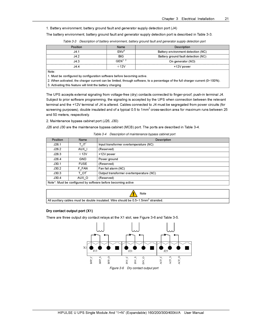
Dry contact output port (X1)
There are three output dry contact relays at the X1 slot, see Figure
X1
| J13 |
|
|
|
|
|
|
|
|
|
|
|
|
|
|
|
|
|
|
|
|
|
|
|
|
|
|
| J21 |
|
|
|
|
| J25 |
|
| ||||
|
|
|
|
|
|
|
|
|
|
|
|
|
|
|
|
|
|
|
| |
BFP C |
|
| BFP S |
| BFP O |
| INV C |
|
|
| INV S |
|
| ACF C |
|
| ACF S |
| ACF O | |
|
|
|
|
|
|
|
| INV O |
| |||||||||||
Figure 3-6 Dry contact output port
HIPULSE U UPS Single Module And “1+N” (Expandable) 160/200/300/400kVA User Manual